This article explains how to prepare an implicit model in nTop for importing and simulating it in SimScale.
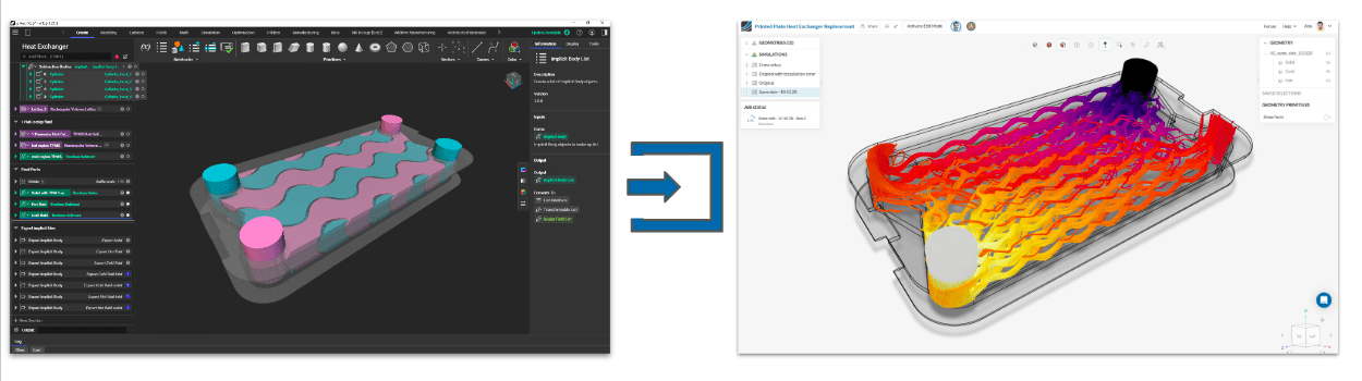
Overview – nTop Implicit
Preparing an implicit model for SimScale import requires three steps:
- Export all relevant implicit bodies
- Export additional auxiliary bodies for face assignments e.g. boundary conditions
- Put all bodies into one compressed archive (zip, tar.gz)
All subsequent workflow steps work exactly the same as for parametric or faceted geometry imports.
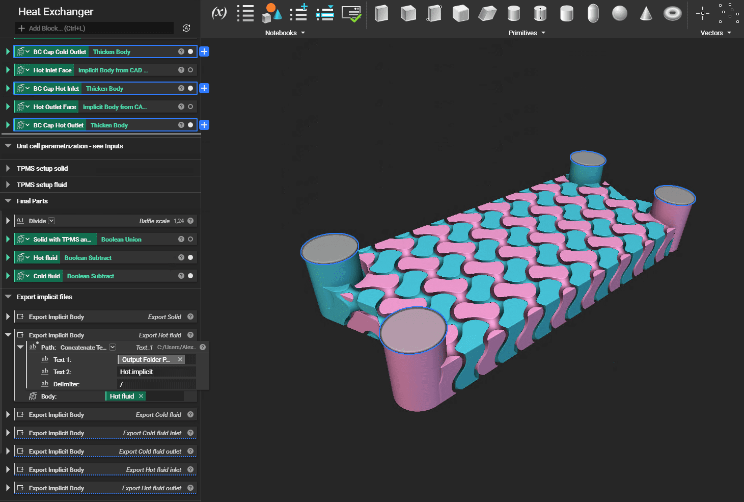
Export Implicit Bodies
All bodies that are required for the simulation should be exported as implicit files using the Export Implicit Body block in nTop.
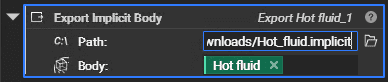
There are no naming restrictions for these implicit bodies. They will appear with the same name in the SimScale user interface.
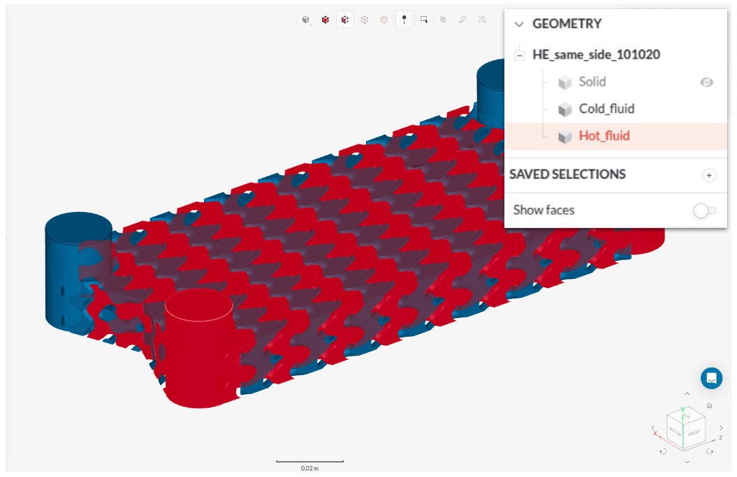
As implicit bodies cannot be edited in SimScale’s CAD editing environment, it is required to export all bodies necessary for the simulation from nTop. That includes all flow regions. Since implicit modeling is extremely robust and fast when dealing with booleans and complex geometrical operations, it is very easy to do so.
Export Auxiliary Bodies for Face Assignment
In order to assign concepts like boundary conditions or result controls in the simulation setup, faces need to be selected and assigned. Implicit models by default do not contain topological boundary information, so the model needs to be enriched accordingly.
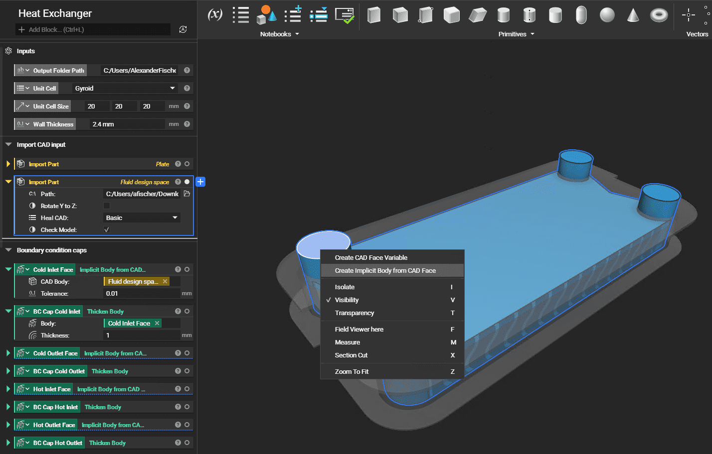
For that purpose, you can create implicit bodies that serve as tool bodies and enclose the respective surface area to split it out and make it accessible for selection. Specifically helpful to create these bodies fast are nTop blocks like,
- Create implicit body from CAD Face plus Thicken or
- Primitives like Create Cylinder or Create Box,
even though it doesn’t matter how the implicit body was created in the end.
It’s recommended to keep the boundaries of the tool body relatively close to the surface area even though SimScale checks for common surface normals to see, for example, if a planar face was intended to be split out. If you can visually distinguish the (transparent) auxiliary and domain parts when zoomed to the full surface area is a good rule of thumb for setting up the tool body thickness. There is no issue if a tool body intersects with additional implicit bodies that do not require the face split.
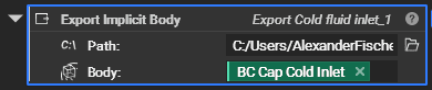
The tool bodies need to be exported as implicit files as well. While domain bodies can be named freely, tool body naming always requires a prefix ‘NS_’ for named selection for SimScale to categorize them correctly and use them for splitting out boundaries. Those faces appear in SimScale in the respective bodies that are contained by them with the name of the tool body without the ‘NS_’ prefix.
Upload Compressed Archive to SimScale
As a last step, you need to put all implicit body exports – the domain bodies and tool bodies – into one compressed archive (e.g., zip or tar.gz) and upload it to SimScale, selecting ‘nTop (.implicit)’ as file format.
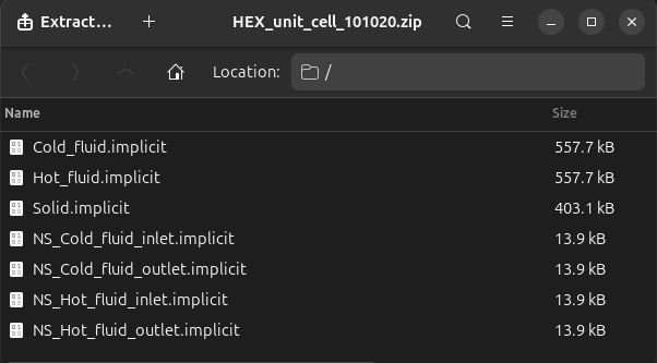
During upload, all tool bodies are identified and used for face splitting, while all domain bodies get imported.
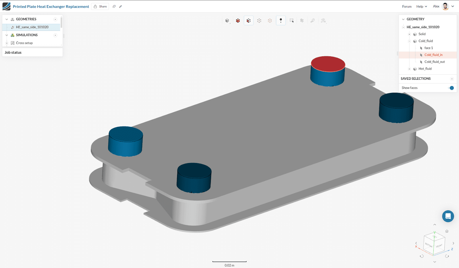
All downstream workflows work exactly the same as for parametric or faceted imports. Note that SimScale also tries to map entities based on the provided naming when geometries get swapped in simulation setups. It is therefore recommended to keep consistent names when doing design iterations.