Error
The clearance between the rotating zone and the rotating parts is too small. Please enlarge the rotating zone and ensure that `Merge CAD Surfaces` is activated in the mesh settings. Increasing the mesh resolution can also help to better resolve the small gaps at the expense of increased computational cost.
What Happened?
To simulate rotating objects the advanced concept of a Moving Reference Frame (MRF) or Arbitrary Mesh Interface (AMI) is used. To do this a rotating zone has been created. The issue is related to the faces of the rotating zone being tangential to the rotating object causing the simulation to fail. An example of such a faulty setup can be seen in Figure 1 below.
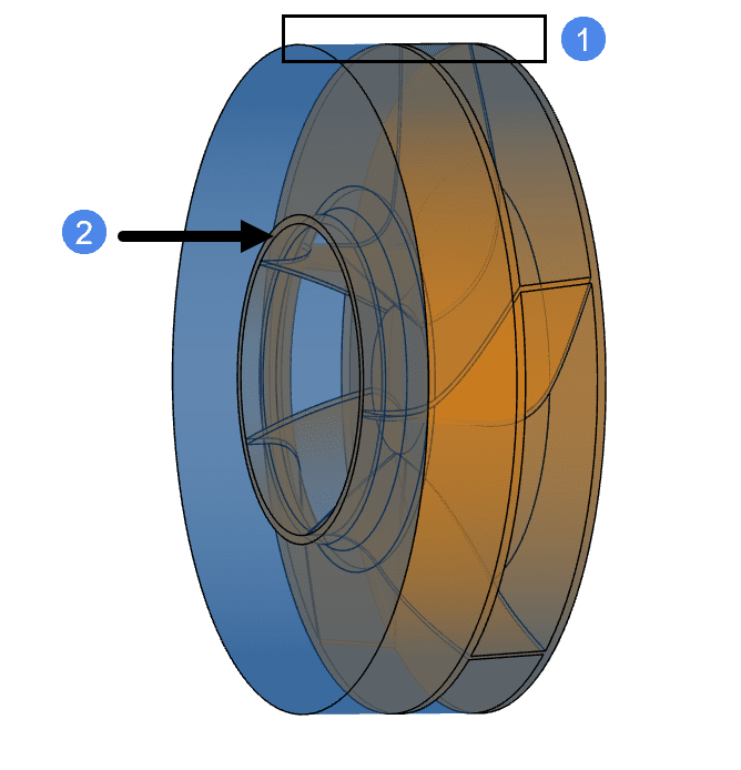
The above example of an incorrect rotating zone highlights two common issues. Point 1 shows that the side surface of the rotating zone cylinder is tangential to the side faces of the turbine geometry, whereas Point 2 shows the planar face of the cylinder being tangential to the turbine geometry.
What Can I Do Now?
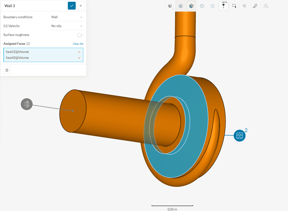
When creating the rotating zone please ensure that the complete rotating body is enclosed in the rotating region. Figure 2 shows an example of a correct rotating zone, where the turbine geometry is fully enclosed in the rotating zone cylinder.

Non-rotating wall Inside a Rotating Zone
If the rotating zone geometry includes surfaces that are non-moving a boundary condition has to be specified for the surface.
Multi-purpose Solver
For the multi-purpose solver, a no-slip wall boundary condition has to be assigned to the non-rotating surfaces inside the rotating zone.
OpenFoam Solver
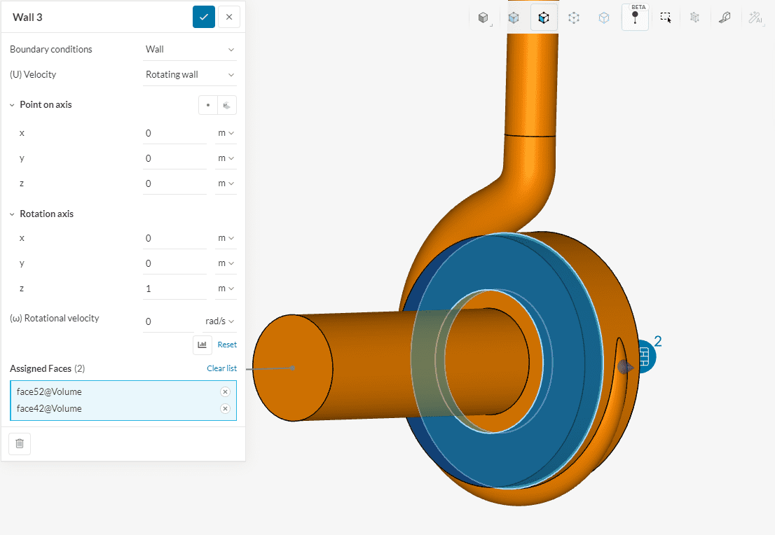
For the OpenFOAM solvers, a rotating wall boundary condition with zero rotational velocity needs to be specified to ensure that no rotational velocity is applied to those surfaces.
Important Information
If none of the above suggestions solved your problem, then please post the issue on our forum or contact us.


