Validation Case: Thermal Bridge Case 2 – Insulated Wall
This thermal bridge validation case belongs to heat transfer. In this project, a simplified wall geometry is validated against analytical data for temperature and heat flux, provided by the EN ISO 10211 Standard, case 2.
Geometry
The geometry for this project is an insulated wall, as seen in Figure 1:
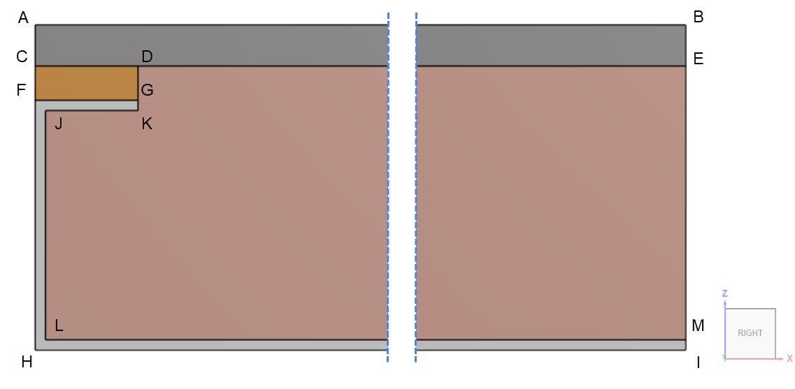
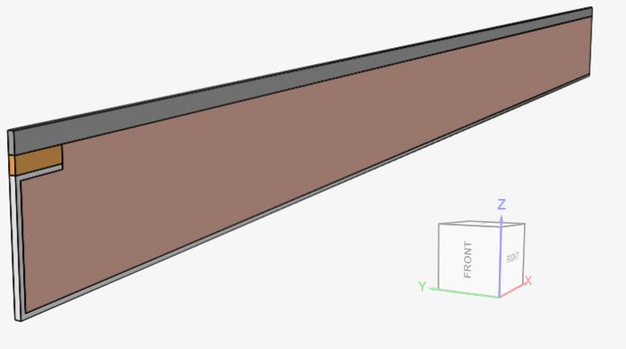
This problem involves a 2D simulation of the insulated door from Figure 1. Since SimScale requires a 3D model to run, the model was extruded by 0.002 meters in the y-direction. An isometric view from the model is shown in Figure 2:
Taking Figure 1 as a reference, the x- and z-coordinates of the points are given below:
| Coordinates | A | B | C | D | E | F | G | H | I | J | K | L | M |
| x \([mm]\) | 0 | 500 | 0 | 15 | 500 | 0 | 15 | 0 | 500 | 1.5 | 15 | 1.5 | 500 |
| z \([mm]\) | 47.5 | 47.5 | 41.5 | 41.5 | 41.5 | 36.5 | 36.5 | 0 | 0 | 35 | 35 | 1.5 | 1.5 |
Analysis Type and Mesh
Tool Type: Code_Aster
Analysis Type: Steady-state heat transfer
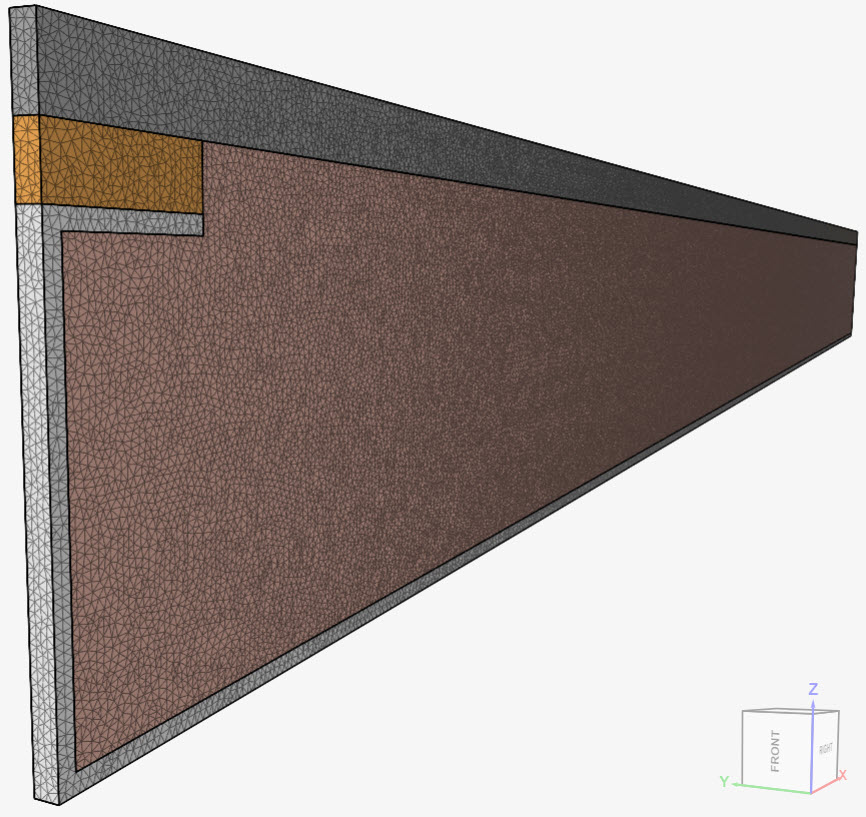
Mesh and Element Types: The mesh used in this simulation was created in SimScale, using the standard mesher. The table below contains an overview of the resulting mesh.
| Case | Mesh Type | Nodes | Element Type |
| EN ISO 10211 Case 2 | Second-order standard | 2011690 | Standard |
In the image below, it’s possible to see the standard mesh in detail:
Simulation Setup
Material: For this validation case, the model consists of 4 materials:
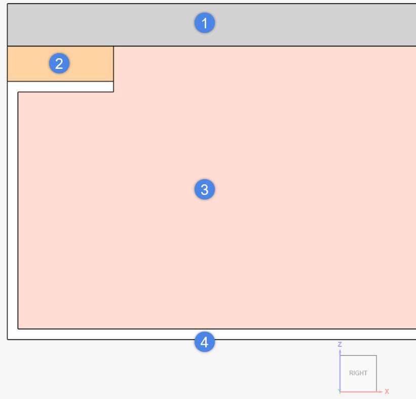
| Material Identification | Thermal Conductivity \([\frac{W}{m.K}]\) | Density \([\frac{kg}{m^3}]\) | Specific Heat \([\frac{J}{kg.K}]\) |
| 1 – Concrete | 1.15, isotropic | 2240 | 750 |
| 2 – Wood | 0.12, isotropic | 500 | 1260 |
| 3 – Insulation (Cork) | 0.029, isotropic | 200 | 350 |
| 4 – Aluminum | 230, isotropic | 2700 | 897 |
Boundary Conditions:
Still using Figure 1 as a reference, the following boundary conditions are defined:
- Convective heat flux boundary condition on the top face AB:
- 0 \(ºC\) Reference temperature
- Heat transfer coefficient of 16.667 \(\frac{W}{m^2.K}\), which is equivalent to a thermal resistance of 0.06 \(\frac{m^2.K}{W}\)
- Convective heat flux boundary condition on the bottom face HI
- 20 \(ºC\) Reference temperature
- Heat transfer coefficient of 9.0909 \(\frac{W}{m^2.K}\), which is equivalent to a thermal resistance of 0.11 \(\frac{m^2.K}{W}\)
Result Comparison
The results obtained with SimScale were compared to those presented in the EN ISO 10211 Standard. According to the aforementioned standard, to satisfy the precision requirements, the temperature differences between the simulation results and the reference values must not exceed 0.1 \(ºC\). Furthermore, the heat flow rate should be within 0.1 \(\frac {W}{m}\) of the analytical solution.
The EN ISO 10211 Standard provides the temperature results on points A, B, C, D, E, F, G, H, I, and also the total flow rate through the wall. The table below provides an overview of the temperature results:
| Point | Analytical \([º C]\) | SimScale \([º C]\) | Difference \([º C]\) | Meets Criteria? (<0.1 \(ºC\)) |
| A | 7.1 | 7.06 | -0.04 | Yes |
| B | 0.8 | 0.76 | -0.04 | Yes |
| C | 7.9 | 7.90 | 0.00 | Yes |
| D | 6.3 | 6.27 | -0.03 | Yes |
| E | 0.8 | 0.83 | +0.03 | Yes |
| F | 16.4 | 16.41 | +0.01 | Yes |
| G | 16.3 | 16.34 | +0.04 | Yes |
| H | 16.8 | 16.77 | -0.03 | Yes |
| I | 18.3 | 18.33 | +0.03 | Yes |
The temperatures found with SimScale for all nine points are well within the acceptance criteria defined by the standard. Furthermore, the ISO standard also provides the analytical solution for the integral heat flux in the z-direction through the wall.
For the Heat Flow rate results, the Heat Flow result control item was used. The average value between the interior and exterior faces is used to account for any numerical deviations. Also, the computed Heat Flow \([W]\) is normalized to the thickness of the model so it is in line with the standard’s results \([W/m]\). The table below shows the results:
| Analytical \([\frac {W}{m}]\) | SimScale Average Heat Flow \([W]\) | SimScale Heat Flow per Unit Thickness \([\frac {W}{m}]\) | Difference \([\frac {W}{m}]\) | Meets Criteria? (<0.1 \([\frac {W}{m}]\)) |
| 9.5 | 0.0189764 | 9.4882 | 0.0118 | Yes |
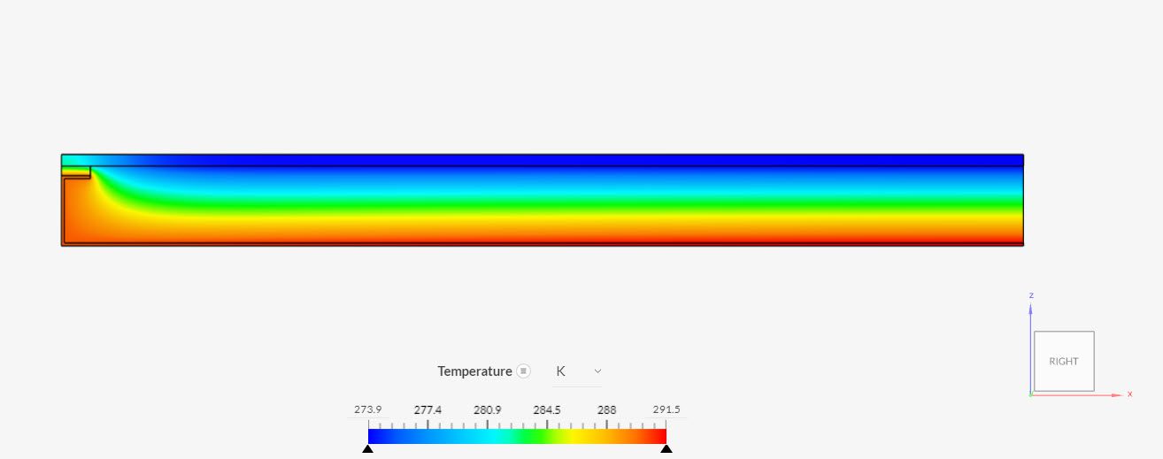
Again, the result obtained with SimScale satisfies the accuracy requirements from the reference standard. Find below the temperature profile observed in the SimScale results:
Since all results obtained with SimScale satisfy the EN ISO 10211 precision requirements, we conclude that SimScale fulfills the accuracy standards for EN ISO 10211 Validation Case 2.
Last updated: August 3rd, 2022
Did this article solve your issue?
How can we do better?
We appreciate and value your feedback.


