Validation Case: Harmonic Analysis of a Straight Beam
This harmonic analysis of a straight beam validation case belongs to solid mechanics. It aims to validate the following parameter:
- Harmonic analysis solver in Simscale
The harmonic analysis results from SimScale were compared to the analytical results from the formulation available in SHLL101\(^1\).
Geometry
Find below the straight beam geometry used for this validation case:
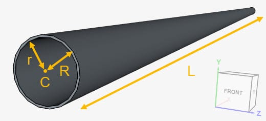
The dimensions of the geometry are tabulated below. Furthermore, the center point C is located at the coordinates (0, 0, 0):
| Geometry Parameter | Dimension \([m]\) |
| Outer radius \((R)\) | 0.0925 |
| Inner radius \((r)\) | 0.08638 |
| Length \((L)\) | 10 |
Analysis Type and Mesh
Tool Type: Code_Aster
Analysis Type: Harmonic analysis
Mesh and Element Types: A total of four meshes are used in this validation case. The standard algorithm was used to create the meshes for cases A and B. The table below contains further information about the cases:
| Case | Mesh Type | Nodes | Element Type | Damping | Load Type |
| Case A1 | Standard | 83973 | 1st order tetrahedral | No | Tension |
| Case A2 | Standard | 83973 | 1st order tetrahedral | No | Bending |
| Case A3 | Standard | 83973 | 1st order tetrahedral | Rayleigh | Tension |
| Case A4 | Standard | 83973 | 1st order tetrahedral | Rayleigh | Bending |
| Case B1 | Standard | 503867 | 2nd order tetrahedral | No | Tension |
| Case B2 | Standard | 503867 | 2nd order tetrahedral | No | Bending |
| Case B3 | Standard | 503867 | 2nd order tetrahedral | Rayleigh | Tension |
| Case B4 | Standard | 503867 | 2nd order tetrahedral | Rayleigh | Bending |
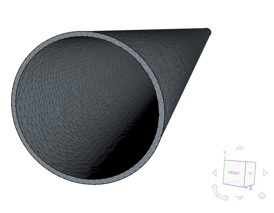
Find below the tetrahedral mesh used for case A:
Simulation Setup
Material:
- Material behavior: Linear elastic
- \((E)\) Young’s modulus = 165.8 \(GPa\)
- \((v)\) Poisson’s ratio = 0.3
- \((\rho)\) Density = 13404.106 \(kg/m^3\)
- Rayleigh damping settings (for the cases that model damping):
- Alpha coefficient = 0.001 \(s\)
- Beta damping = 0 \(1/s\)
Boundary Conditions:
- Constraint:
- The free end of the cylinder at \(x\) = 0 is a Fixed support
- Load:
- The other free end of the cylinder, at \(x\) = 10 \(m\), receives a bending or a tension load, according to table 2.
- Tension load: Force boundary condition, with \(F_x\) = 3000 \(N\)
- Bending load: Force boundary condition, with \(F_y\) = 3000 \(N\)
- The other free end of the cylinder, at \(x\) = 10 \(m\), receives a bending or a tension load, according to table 2.
Reference Solution
The analytical solution for the displacements, velocity, and acceleration on the point (10, 0, 0) are presented in SHLL101\(^1\).
Note
The point (10, 0, 0), where the reference results were calculated, is the center point of the annulus.
As this point is not within the solid walls of the pipe, a total of 4 points were created on the free end to assess the results:
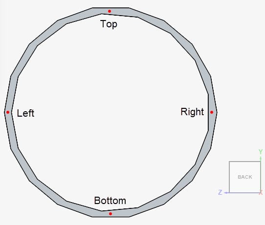
The coordinates of the points are as follows:
– Left: (10, 0, 0.08944)
– Right: (10, 0, -0.08944)
– Top: (10, 0.08944, 0)
– Bottom: (10, -0.08944, 0)
SimScale results are the average of the values obtained at these four points. When tension is being applied, the results are evaluated in the x-direction. Otherwise, if a bending load is applied, the results are taken in the y-direction.
Result Comparison
In Table 3, we compare SimScale results with the reference SHLL101\(^1\), modeling tension load, and no damping.
| Case | Displacement in x-direction [\(m\)] | Error [%] | Velocity in x-direction [\(m/s\)] | Error [%] | Acceleration in x-direction [\(m/s^2\)] | Error [%] |
| SHLL101 (Real) | 5.3180E-05 | – | 0 | – | -2.0990E-01 | – |
| SHLL101 (Imaginary) | 0 | – | 3.3410E-03 | – | 0 | – |
| Case A1 (Real) | 5.3433E-05 | 0.4735 | 0 | 0 | -2.1095E-01 | 0.4973 |
| Case A1 (Imaginary) | 0 | 0 | 3.3580E-03 | 0.5060 | 0 | 0 |
| Case B1 (Real) | 5.3105E-05 | -0.1409 | 0 | 0 | -2.0965E-01 | -0.1188 |
| Case B1 (Imaginary) | 0 | 0 | 3.3367E-03 | -0.1292 | 0 | 0 |
Table 4 shows a similar comparison, but now for the cases with a bending load and no damping.
| Case | Displacement in y-direction [\(m\)] | Error [%] | Velocity in y-direction [\(m/s\)] | Error [%] | Acceleration in y-direction [\(m/s^2\)] | Error [%] |
| SHLL101 (Real) | -2.1160E-02 | – | 0 | – | 8.3550E+01 | – |
| SHLL101 (Imaginary) | 0 | – | -1.3300E+00 | – | 0 | – |
| Case A2 (Real) | -2.1066E-02 | -0.4443 | 0 | 0 | 8.3167E+01 | -0.4606 |
| Case A2 (Imaginary) | 0 | 0 | -1.3236E+00 | -0.4805 | 0 | 0 |
| Case B2 (Real) | -2.1066E-02 | -0.4443 | 0 | 0 | 8.3167E+01 | -0.4606 |
| Case B2 (Imaginary) | 0 | 0 | -1.3237E+00 | -0.4797 | 0 | 0 |
Now, comparing the cases with tension load and the Rayleigh damping model:
| Case | Displacement in x-direction [\(m\)] | Error [%] | Velocity in x-direction [\(m/s\)] | Error [%] | Acceleration in x-direction [\(m/s^2\)] | Error [%] |
| SHLL101 (Real) | 5.2960E-05 | – | 2.1130E-04 | – | -2.0910E-01 | – |
| SHLL101 (Imaginary) | -3.3630E-06 | – | 3.3270E-03 | – | 1.3270E-02 | – |
| Case A3 (Real) | 5.3219E-05 | 0.4859 | 2.1237E-04 | 0.5038 | -2.1010E-01 | 0.4764 |
| Case A3 (Imaginary) | -3.3800E-06 | 0.5021 | 3.3439E-03 | 0.5045 | 1.3344E-02 | 0.5516 |
| Case B3 (Real) | 5.3226E-05 | 0.4998 | 2.1262E-04 | 0.6208 | -2.1007E-01 | 0.4603 |
| Case B3 (Imaginary) | -3.3758E-06 | 0.3803 | 3.3433E-03 | 0.4881 | 1.3359E-02 | 0.6684 |
Lastly, the results for bending load and damping are compared in Table 6:
| Case | Displacement in y-direction [\(m\)] | Error [%] | Velocity in y-direction [\(m/s\)] | Error [%] | Acceleration in y-direction [\(m/s^2\)] | Error [%] |
| SHLL101 (Real) | -2.1020E-02 | – | 1.1460E-01 | – | 8.2980E+01 | – |
| SHLL101 (Imaginary) | -1.8230E-03 | – | -1.3210E+00 | – | 7.1980E+00 | – |
| Case A4 (Real) | -2.0924E-02 | -0.4583 | 1.1325E-01 | -1.1903 | 8.2605E+01 | -0.4537 |
| Case A4 (Imaginary) | -1.8025E-03 | -1.1390 | -1.3147E+00 | -0.4784 | 7.1159E+00 | -1.1542 |
| Case B4 (Real) | -2.0924E-02 | -0.4583 | 1.1325E-01 | -1.1894 | 8.2605E+01 | -0.4537 |
| Case B4 (Imaginary) | -1.8025E-03 | -1.1390 | -1.3147E+00 | -0.4784 | 7.1159E+00 | -1.1542 |
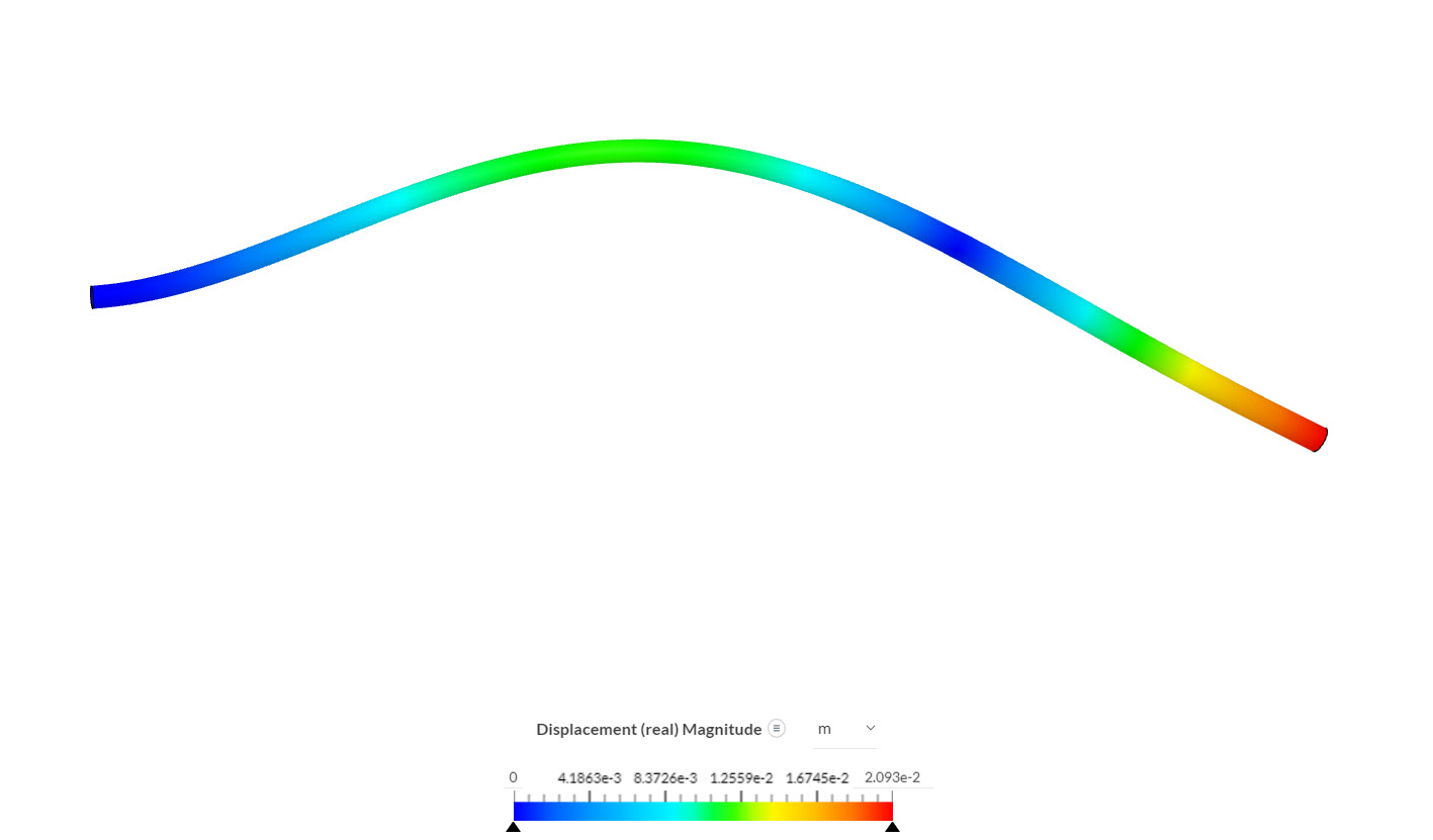
SimScale results show great agreement with the analytical solution for all configurations.
Inspecting the displacement magnitude for case B4 in the post-processor:
References
Last updated: April 21st, 2026
Did this article solve your issue?
How can we do better?
We appreciate and value your feedback.


