Documentation
This plane strain condition validation case belongs to solid mechanics. This test case aims to validate the following parameters:
The simulation results from SimScale were compared to the analytical results presented in [SSLV04]\(^1\).
The geometry used for the case is as follows:
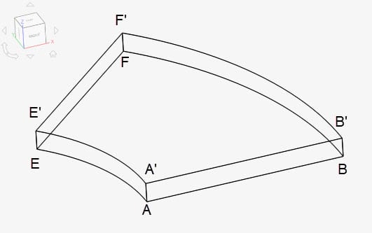
The 3D geometry is a 45-degree section of a hollow cylinder with dimensions as tabulated below:
| A | B | E | F | A’ | B’ | E’ | F’ | |
| x | 0.1 | 0.2 | 0.0707 | 0.1414 | 0.1 | 0.2 | 0.0707 | 0.1414 |
| y | 0 | 0 | 0.0707 | 0.1414 | 0 | 0 | 0.0707 | 0.1414 |
| z | 0 | 0 | 0 | 0 | 0.01 | 0.01 | 0.01 | 0.01 |
Tool Type: Code Aster
Analysis Type: Static linear
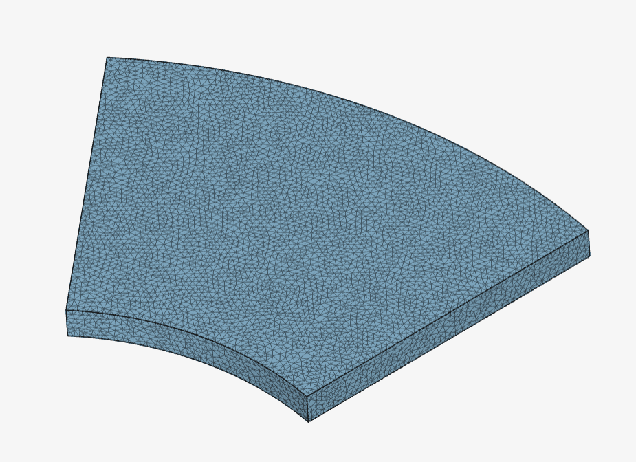
Mesh and Element Types: The meshes used in this project were created using the standard meshing tool on the SimScale platform. In Table 2 you will find a summary of the mesh characteristics.
| Case | Mesh Type | Number of Cells | Number of Nodes | Element Type |
| (A) | Standard | 150813 | 30834 | 1st order tetrahedral |
| (B) | Standard | 150813 | 222478 | 2nd order tetrahedral |
Find below the manually refined 2st order standard mesh used in Case B:
Material:
Boundary Conditions:
The analytical solution is given by the equations presented under Reference Solution\(^1\).
The results obtained from SimScale for displacements, stresses, and strains at point A are compared with those presented in SSLV04.
| Case | Quantity | [SSLV04] | SimScale | Error [%] |
| (A) | Displacement \(dx\ [m]\) | 5.90e-05 | 5.72e-05 | -3.05 |
| (B) | Displacement \(dx\ [m]\) | 5.90e-05 | 5.72e-05 | -3.05 |
| (A) | Cauchy Stress \(\sigma_{xx}\ [MPa]\) | -6.00e01 | -5.89e01 | -1.83 |
| (B) | Cauchy Stress \(\sigma_{xx}\ [MPa]\) | -6.00e01 | -5.99e01 | -0.16 |
| (A) | Cauchy Stress \(\sigma_{yy}\ [MPa]\) | 1.00e02 | 1.00e02 | 0 |
| (B) | Cauchy Stress \(\sigma_{yy}\ [MPa]\) | 1.00e02 | 1.00e02 | 0 |
| (A) | Total Strain \(\epsilon_{xx} \) | -4.50e-04 | -4.63e-04 | 2.89 |
| (B) | Total Strain \(\epsilon_{xx} \) | -4.50e-04 | -4.67e-04 | 3.78 |
| (A) | Total Strain \(\epsilon_{yy} \) | 5.90e-04 | 5.75e-04 | -2.54 |
| (B) | Total Strain \(\epsilon_{yy} \) | 5.90e-04 | 5.72e-04 | -3.05 |
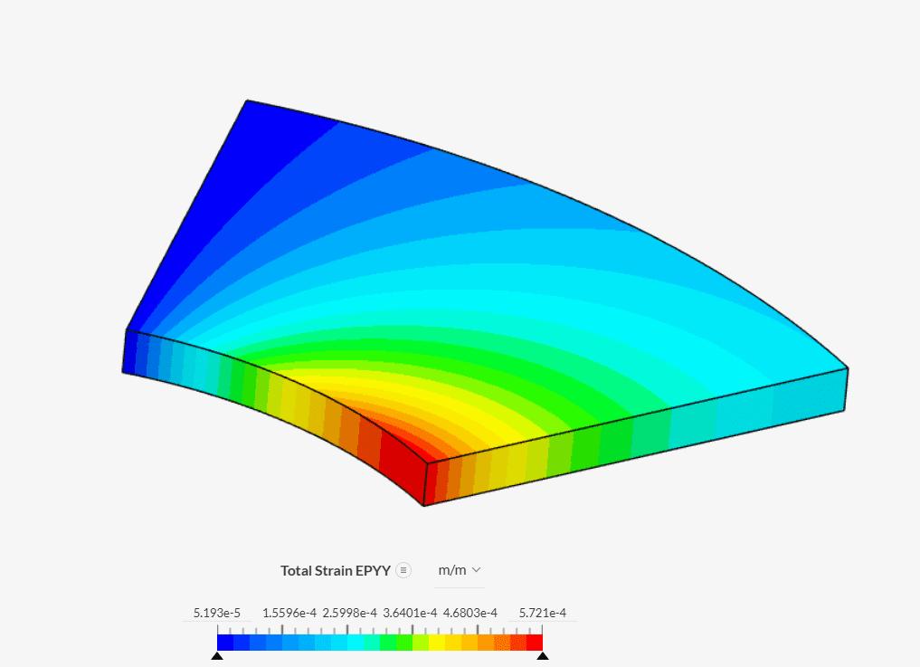
Find in Figure 3 below the Case B results for the total strain \(\epsilon_{yy}\) distributed across the cylinder:
Last updated: June 15th, 2025
We appreciate and value your feedback.
Sign up for SimScale
and start simulating now