
Validation Case: Cantilever Plate Subjected to a Follower Pressure
This validation case belongs to solid mechanics. It uses a cantilever plate geometry to validate the follower pressure boundary condition.
SimScale results are compared to simulation results, presented in [SSNV145]\(^1\). The reference uses Code_Aster to perform the analysis.
Geometry
The geometry for this project consists of a cantilever plate, as seen in Figure 1:
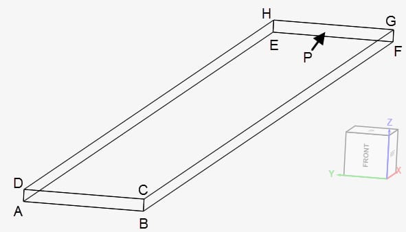
The dimensions of the geometry are given in Table 1:
| Coordinates | A | B | C | D | E | F | G | H | P |
| x \([m]\) | 0 | 0 | 0 | 0 | 10 | 10 | 10 | 10 | 10 |
| y \([m]\) | 0.5 | -0.5 | -0.5 | 0.5 | 0.5 | -0.5 | -0.5 | 0.5 | 0 |
| z \([m]\) | -0.05 | -0.05 | 0.05 | 0.05 | -0.05 | -0.05 | 0.05 | 0.05 | 0 |
Analysis Type and Mesh
Tool Type: Code_Aster
Analysis Type: Nonlinear static
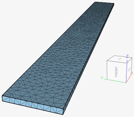
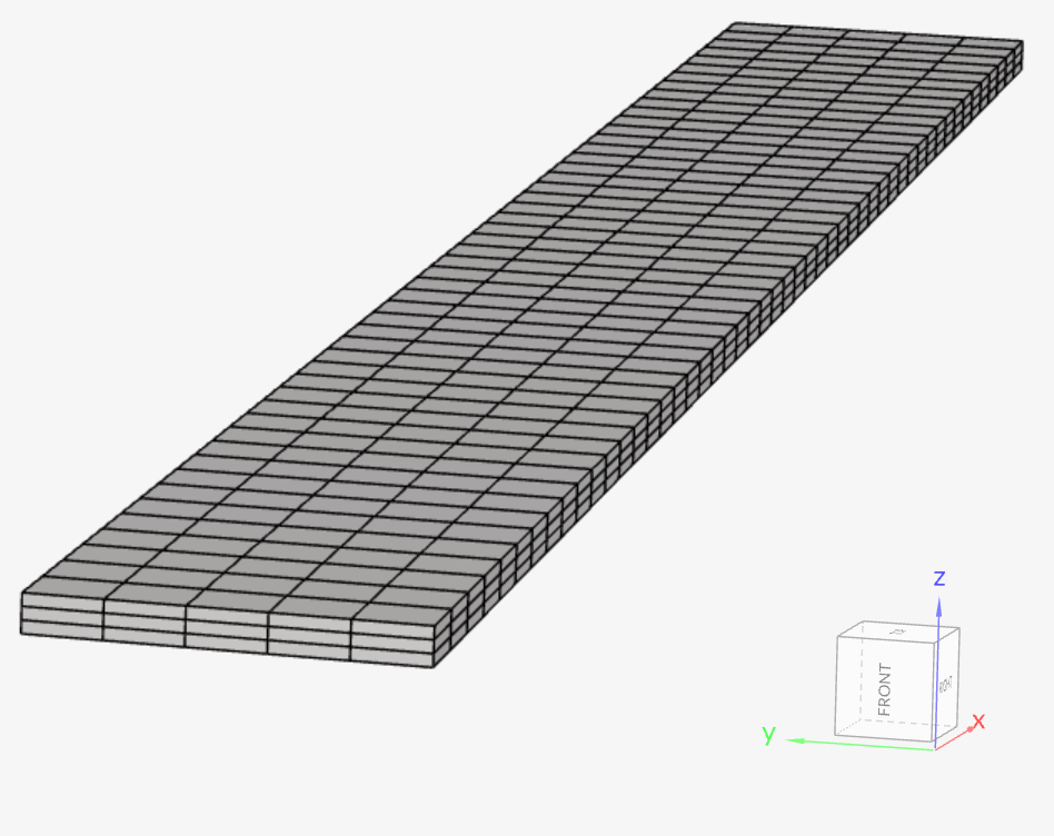
Mesh and Element Types: Two meshes are used in this case. The first one is a second-order mesh created in SimScale with the standard algorithm. Case B uses a second-order hexahedral mesh created in SimScale with an extrusion refinement.
Table 2 contains details of the resulting meshes:
| Case | Mesh Type | Nodes | Element Type |
| A | Second-order standard | 9700 | Standard |
| B | Second-order hexahedral | 4362 | Standard |
Figure 2 shows the standard mesh, used for case A:
Similarly, Figure 3 shows the second-order hexahedral mesh, that was imported to SimScale.
Note
Especially for nonlinear analysis, such as this one, we recommend second-order meshes. They provide more accurate results, due to the higher number of nodes.
The following article provides further information on second-order meshes for finite element analysis.
Simulation Setup
Material:
- Material behavior: Linear elastic
- \((E)\) Young’s modulus = 1.2e+7 \(Pa\)
- \((\nu)\) Poisson’s ratio = 0.3
- \((\rho)\) Density = 1000 \(kg/m³\)
Boundary Conditions:
The boundary conditions will be defined based on Figure 1:
- Constraints
- Fixed support on face ABCD
- Surface loads
- Follower Pressure \(P\), applied on face CDHG. The following formulation is used:
$$P = t \tag{1}$$
Where \(t\) is the pseudo-time for the nonlinear analysis. This validation case will run until \(t\) = 26.
- Follower Pressure \(P\), applied on face CDHG. The following formulation is used:
Result Comparison
SimScale results will be compared against two reference simulations. The first one used Code_Aster, while the remaining one used the SAMCEF software.
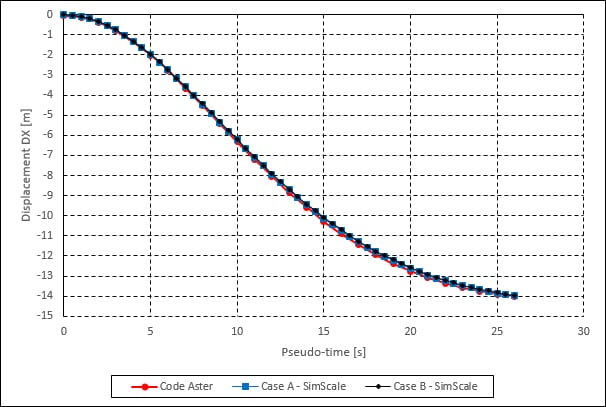
The results for both reference simulations are found in [1]. The displacements in the X and Z-directions are evaluated at point P (as seen in Figure 1).
In Figure 4, we compare the results for the displacements in the X-direction against Code_Aster. The reference results were extracted using WebPlotDigitizer.
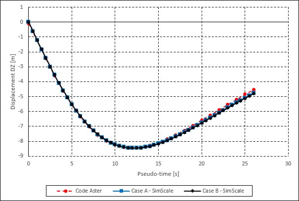
A similar comparison was made for the displacements in the Z-direction:
Additionally, still using point P as a reference, the displacements obtained with SimScale are compared to the results from the SAMCEF software\(^1\). Table 1 contains the displacements in the X-direction:
| Pseudo-time \([s]\) | SAMCEF – DX \([m]\) | Case A – DX \([m]\) | Error [%] | Case B – DX \([m]\) | Error [%] |
| 11 | -7.3664 | -7.0953 | -3.68 | -7.0823 | -4.01 |
| 13 | -9.03743 | -8.7143 | -3.58 | -8.6969 | -3.92 |
| 22 | -13.5098 | -13.2380 | -2.01 | -13.2169 | -2.22 |
| 26 | -14.1513 | -13.9797 | -1.21 | -13.9645 | -1.34 |
A comparison for the displacements in the Z-direction is also presented:
| Pseudo-time \([s]\) | SAMCEF – DZ \([m]\) | Case A – DZ \([m]\) | Error [%] | Case B – DZ \([m]\) | Error [%] |
| 11 | -8.44920 | -8.3929 | -0.67 | -8.3907 | -0.70 |
| 13 | -8.42753 | -8.4310 | 0.04 | -8.4316 | 0.048 |
| 22 | -5.78828 | -6.0759 | 4.97 | -6.0972 | 5.34 |
| 26 | -4.43375 | -4.7696 | 7.57 | -4.7969 | 8.19 |
The results obtained with SimScale for both directions show a great agreement with the reference simulations.
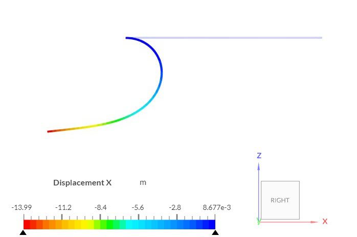
Figure 6 shows the contours for displacements in the X-direction, for case A. The follower pressure boundary condition is updated after each pseudo time step, based on the current deformed state of the geometry. As a result, the plate gets rolled up:
Last updated: April 3rd, 2026
Did this article solve your issue?
How can we do better?
We appreciate and value your feedback.






