Documentation
Busbars are metallic strips or bars that function as conductors, centralizing the electric power at a single location and enhancing the efficiency of power distribution in various industries. Most power applications rely heavily on busbars as they serve as the main conduits linking the power module to the external environment.
Despite ongoing design developments over the past few decades in the power, motor, industrial, and automotive industries, busbars remain pivotal to power distribution and vital for industries ranging from manufacturing to renewable energy. Their usage underpins the efficiency and reliability of electrical systems globally. In 2022, the busbar market was valued at just over USD 15 billion, with projections suggesting a growth up to almost USD 24 billion by 2030.
Busbar applications span various settings, including factories, data centers, retail facilities, laboratories, and technology-oriented environments. This article will help engineers gain a fundamental understanding of busbars, their types, applications, and the specific challenges encountered in their implementation. We will also discuss how engineering simulations can help overcome these challenges, focusing on how SimScale helps this process.
A busbar is a metallic strip or bar commonly found inside switchgear, panel boards, and busway enclosures. It serves a crucial role in local high-current power distribution. It acts as a conductor or group of conductors that collects electric power from incoming feeders and distributes it to outgoing feeders. Functioning as an electrical junction where all incoming and outgoing electrical currents converge, a busbar centralizes the electric power at a single location.
The primary aim of busbars is to enhance system efficiency. They offer an effective solution for complex electrical systems by providing a streamlined approach to power distribution. Busbars are typically made from copper or aluminum.
The busbar system incorporates isolators and circuit breakers. In the event of a fault, the circuit breaker trips off, allowing the faulty section of the busbar to be swiftly disconnected from the circuit.
This mechanism ensures that disruptions are localized, prevents faults from spreading throughout the system, and maintains the integrity and reliability of the power distribution network.
Electrical busbars are categorized into three primary systems, i.e., single, double, and ring.
The single busbar system, characterized by a straightforward design, directly connects all switches and circuits to a solitary busbar. It stands out for its cost efficiency and ease of maintenance, making it a go-to system for less complex installations. However, its major drawback is the lack of redundancy; any fault can hinder the entire system, potentially leading to significant operational downtime.
Featuring two parallel busbars, the double busbar system is tailored for environments where continuity is crucial. This configuration allows for operational flexibility, as circuits can be shifted between busbars without halting the power supply. While it increases system reliability and minimizes outage risks, the increased complexity, cost, and spatial requirements might be limiting factors.
The ring busbar system employs a ring configuration, connecting circuits in a loop, with each having access to two busbars for enhanced redundancy. It is predominantly utilized in distribution networks and maintains service continuity even when one segment fails. The ring system’s resilience comes at the cost of higher design and load management complexity, demanding meticulous planning for efficient performance.
Busbars are integral components in various industries, including:
Accurate simulation of busbars is fundamental to optimizing their performance and reliability in electrical systems. Here are the important simulation parameters to look at:
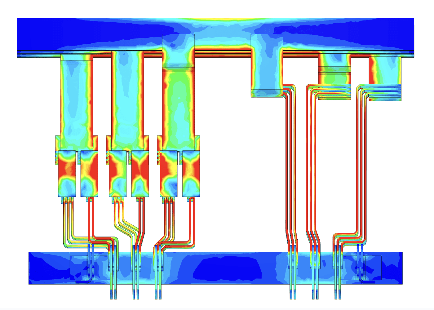
In busbars, eddy currents can cause significant energy losses and may lead to overheating, impacting the busbar’s efficiency and lifespan. Accurately simulating eddy currents enables engineers to predict these losses and thermal effects.
Engineers use laminated busbar structures in areas prone to high magnetic flux. Laminations break up the conductive path for eddy currents, reducing their intensity.
Ohmic or resistive losses are critical factors in busbar design that directly impact efficiency and thermal performance. To minimize these losses, opt for materials with low electrical resistivity, such as copper or aluminum. The most common method is to increase the busbar’s cross-sectional area. A thicker busbar has lower resistance, which reduces ohmic losses.
Simulating ohmic losses in busbars can help optimize their design and performance and compare different design parameters to ensure minimal resistance and energy loss.
The mechanical strength of a busbar is essential for its durability and reliability, especially in environments subjected to vibrations, thermal expansion, or mechanical stress. Analyzing the mechanical properties of busbars using finite element analysis (FEA) and simulation can provide thorough insights into the part’s durability against vibration or other types of stresses.
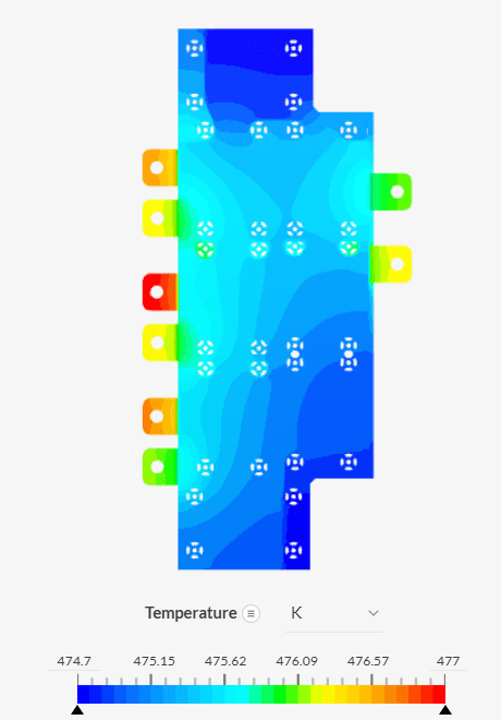
Excessive temperature increases can degrade materials, compromise electrical connections, and elevate the risk of failure. Engineers can evaluate how different load conditions, ambient temperatures, and installation configurations affect the busbar’s temperature through simulation.
Busbars don’t operate in isolation; they’re part of larger electrical systems. Their simulation presents engineers with some challenges because they often feature intricate shapes and bends to fit specific applications.
Traditional simulation software often demands extensive hardware and time resources, which can be a significant barrier for engineers to innovate and optimize their designs quickly. To overcome this barrier, SimScale offers a cloud-native simulation platform that operates directly through your web browser, removing the need for specialized hardware or installations. It allows engineers to perform complex simulations in parallel without requiring upfront investment in powerful computing infrastructure.
Furthermore, busbars necessitate careful examination of parameters like electrical current, thermal effects, and structural integrity, often all at once. SimScale enables engineers and designers to conduct various types of analysis in parallel, such as simultaneously assessing thermal management and electromagnetic behavior.
Additionally, electrical loads on busbars are rarely constant; they fluctuate based on demand, maintenance schedules, and unexpected failures. Simulating dynamic loading conditions to predict how a busbar will respond to these changes is crucial for designing a system that can withstand real-world operations.
Time-harmonic magnetics, an electromagnetic simulation feature from SimScale, is essential for understanding and simulating electromagnetic phenomena. It operates on the principles outlined by Maxwell’s equations under time-harmonic conditions.
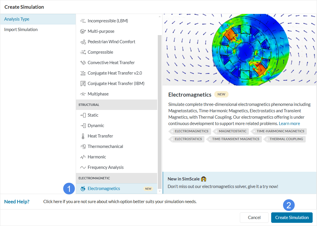
When materials are exposed to sinusoidal excitations, the resultant electric and magnetic fields, as well as the currents, exhibit a sinusoidal time variation. This scenario is common in busbar applications, where alternating current is the norm.
SimScale implements a time-harmonic magnetic low-frequency approximation of Maxwell’s equations, focusing on scenarios where the displacement current can be neglected for simplicity and efficiency. This approximation, while simplifying the equations, remains robust for low-frequency applications pertinent to busbars, such as:
Start your busbar simulation in the cloud now. Create a SimScale account online in minutes by clicking the “Start Simulating” button below. No installation, special hardware, or credit card is required.
Last updated: January 7th, 2025
We appreciate and value your feedback.
What's Next
Wireless Power Transfer: An OverviewSign up for SimScale
and start simulating now