Follower Pressure
The follower pressure boundary condition belongs to solid mechanics applications. More specifically, it can be created in nonlinear static, dynamic, and nonlinear thermomechanical analysis types.
Follower Pressure Setup
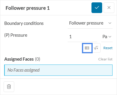
This boundary condition results in a distributed load, normal to the assigned entities. Figure 1 shows the setup window for this boundary condition. By clicking on the highlighted button, it’s also possible to define the (P) Pressure value via a table or formula input:
In contrast to the ordinary pressure boundary condition, the follower pressure is inherently nonlinear, as it will dynamically adapt during the simulation. The following conditions are taken into account:
- The current deformed state of the surface
- Any changes in the direction of the normals of assigned entities
- Changes in the surface area of the assigned faces
This dependence on the deformed state of the geometry makes this a nonlinear boundary condition type. Therefore, it is not applicable in any linear analysis type, such as linear static and harmonic.
Follower Pressure vs Pressure
Find below a nonlinear study, comparing both pressure boundary conditions applied to a beam. The setup for both cases is identical, except for the type of boundary condition.
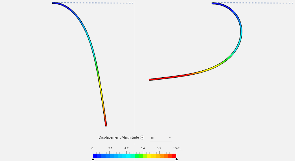
On the right part in Figure 2, the pressure is being applied to the top face of the beam. The dotted line indicates the original, undeformed beam structure before pressure was applied. As the beam starts to undergo deformation, the follower pressure adapts to the new configuration, always applying forces normal to the top face.
The left part of Figure 2 shows the results for an ordinary pressure boundary condition:
Once again, the dotted line indicates the initial beam position. The resulting displacement is very different from the follower pressure boundary condition since the pressure boundary condition won’t dynamically adapt to the beam’s deformations.
Last updated: July 8th, 2025
Did this article solve your issue?
How can we do better?
We appreciate and value your feedback.


