Hinge Constraint
The Hinge constraint boundary condition replicates the behavior of a fixed hinge. The assigned surface is constrained such that only rotational motion around the hinge axis is free. SimScale can automatically detect the axis of the hinge based on an assigned cylindrical surface, but the boundary condition also allows for a user-defined input.
Supported Analysis Types
The following analysis types support the usage of the hinge boundary condition:
Defining in the Workbench
The settings panel for the hinge constraint boundary condition, with automatic detection of the axis origin and direction, is shown in Figure 1:
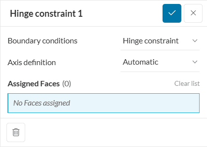
- Assigned Faces: Select a face or a saved selection.
Figure 2 shows the setup options for a custom axis definition.
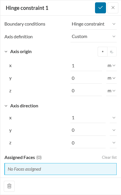
- Axis Origin: Define the reference point of the axis.
- Axis direction: Define the axis direction as a vector.
- Assigned Faces: Select a face or a saved selection.
Cylindrical face assignment
When using the automatic axis definition, only select cylindrical faces, as this is a requirement to accurately detect the rotating axis. When a custom axis is defined, non-cylindrical faces can also be selected.
Assignment of Faces
Please be aware that the hinge constraint boundary condition only allows for single face assignment. Assigning more than one face will lead to the following warning.
“Only one face assignment is allowed. Problematic boundary condition: Cylindrical hinge constraint 1”
The following constraints for displacement \( D\) and rotation \( R\) will be applied to the selected face in the X, Y, and Z directions.
\( DX = 0 \)
\( DY = 0\)
\( DZ = 0\)
and
\( RX = about\ X-axis\ only\) or
\( RY = about\ Y-axis\ only\) or
\( RZ = about\ Z-axis\ only\)
Small Rotating Motions
Please be aware that the the hinge boundary condition only allows for small rotating motions.
Example
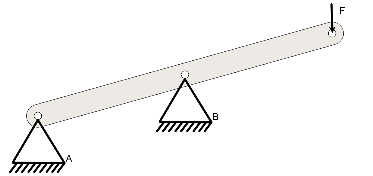
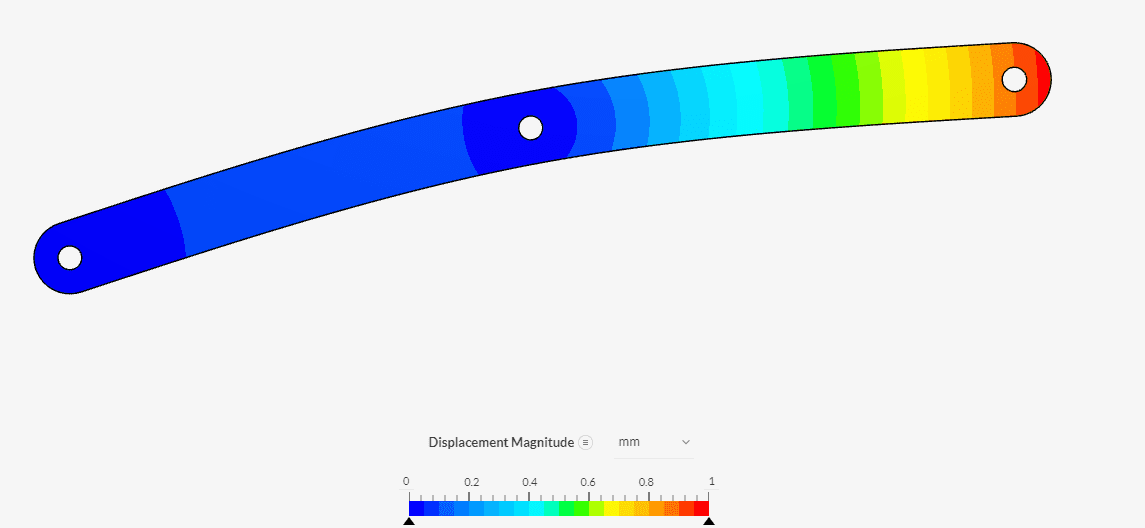
Below is an example of the hinge constraint boundary condition. The part is fixed with two hinges in points A and B and a force F of 1 \( kN\) is applied. So when applying the load the deformed part can rotate on these two hinge points.
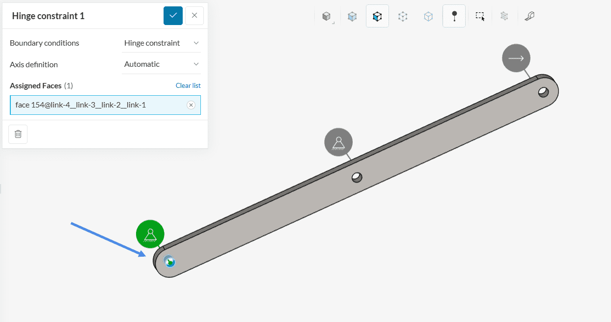
The setup for point A can be seen in Figure 4 below. Here the automatic detection of the axis origin and axis direction is used. Equivalent point B is also set up this way.
The result of the simulation can be seen in the image below. As expected the beam can rotate on the two hinge points forming an arch between the two hinge points.
Alternative for setting up a hinge constraint boundary condition
As an alternative to the Hinge boundary condition a Remote displacement boundary condition can be used.
Last updated: March 12th, 2025
Did this article solve your issue?
How can we do better?
We appreciate and value your feedback.


