Validation Case: Design Analysis of a Spherical Pressure Vessel
This design analysis of a spherical pressure vessel validation case belongs to thermomechanics. This test case aims to validate the following parameters:
- Transient thermostructural analysis
The simulation results of SimScale were compared to the analytical results presented in [Afkar]\(^1\).
Geometry
The geometry consists of 1/8th of a sphere, with an inner radius of 0.19 \(m\) and an outer radius of 0.2 \(m\).
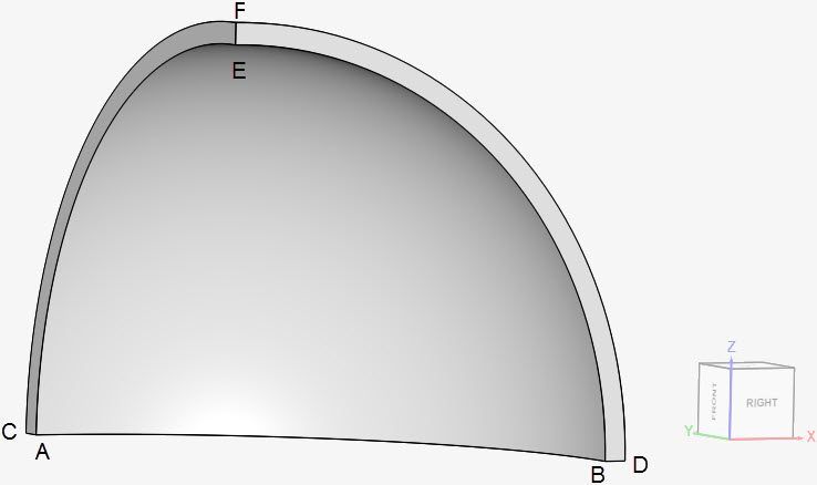
The coordinates for the points in the sphere are as tabulated below:
| A | B | C | D | E | F | |
| x | 0 | 0.19 | 0 | 0.2 | 0 | 0 |
| y | 0.19 | 0 | 0.2 | 0 | 0 | 0 |
| z | 0 | 0 | 0 | 0 | 0.19 | 0.2 |
Analysis Type and Mesh
Tool Type: Code_Aster
Analysis Type: Transient thermomechanical, linear
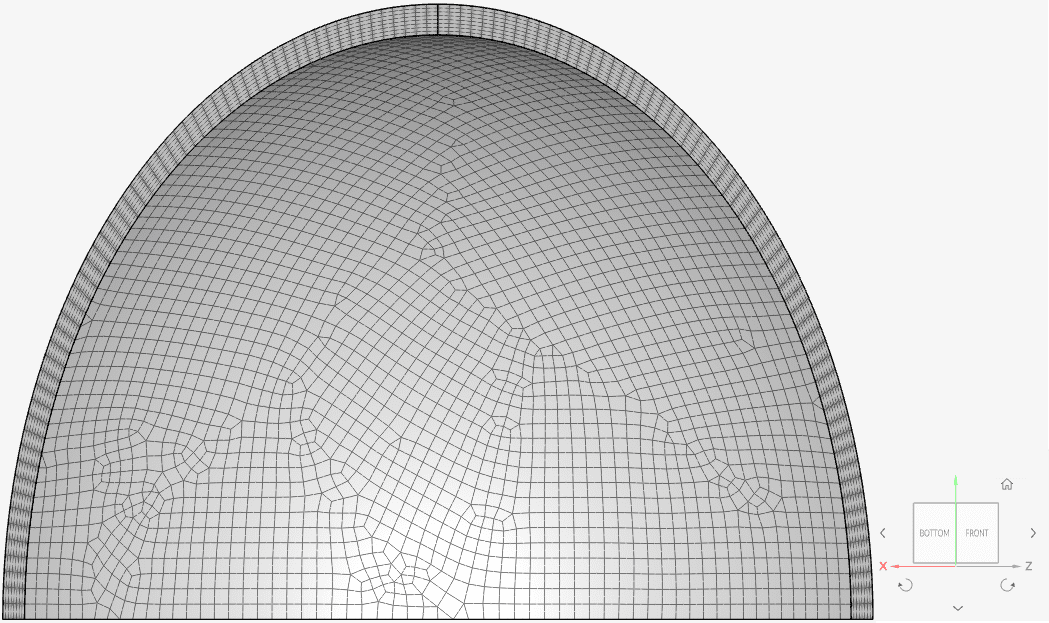
Mesh and Element Types: The mesh for cases A and B was created with the standard algorithm coupled with a quad-dominant extrusion refinement along the thickness of the vessel. A second order mechanical element and first order thermal element with lumped mass were considered.
The setup from cases A and B is the same, except for the thermal conductivity \(\kappa\).
| Case | Mesh Type | Nodes | Thermal Conductivity \(\kappa\) | Element Type |
| (A) | 2nd order Standard | 87962 | 20 \([\frac {W}{m.K}]\) | Hex-dominated |
| (B) | 2nd order Standard | 87962 | 22 \([\frac {W}{m.K}]\) | Hex-dominated |
Find below the mesh used for both cases. It’s a standard mesh with second order hexahedral-dominant elements.
Simulation Setup
Material:
- Steel (linear elastic)
- \(E\) = 190 \(GPa\)
- \(\nu\) = 0.305
- \(\rho\) = 7750 \(kg/m³\)
- \(\kappa\) = 20 \([\frac {W}{m.K}]\) and 22 \([\frac {W}{m.K}]\) for cases A and B, respectively;
- Expansion coefficient = 9.7e-6 \(1/K\)
- \(T_0\) Reference temperature = 300 \(K\)
- Specific heat = 486 \(\frac {J}{kg.K}\)
Initial Conditions
Temperature is 300 \(K\) in the entire pressure vessel.
Boundary Conditions:
- Constraints
- \(d_x\) = 0 on face ACFE;
- \(d_y\) = 0 on face BDFE;
- \(d_z\) = 0 on face ACDB.
- Surface loads
- Pressure boundary condition on face ABE. The pressure increases linearly from 0 \(MPa\) to 1 \(MPa\) according to formula \(P = (0.2e6).t\), where \(t\) is time from 0 to 5 seconds;
- Fixed temperature value boundary condition on face ABE. Temperature is increasing linearly, from 300 \(K\) to 500 \(K\) according to formula \(T = 40.t + 300\), where \(t\) is time from 0 to 5 seconds;
- Convective heat flux boundary condition on face CFD. The heat transfer coefficient is 90 \(\frac {W}{K.m^2}\) and \(T_0\) reference temperature is 300 \(K\).
Reference Solution
The analytical solution is given by the equations presented in [Afkar]\(^1\).
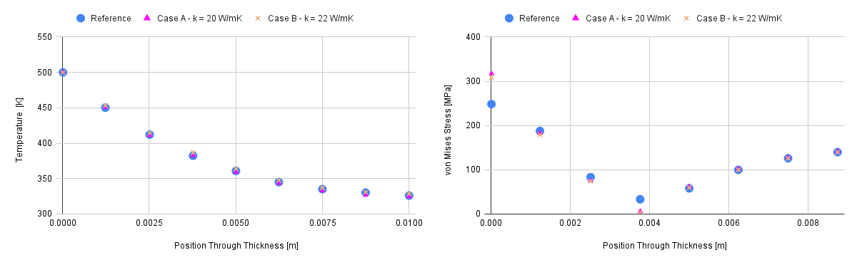
Result Comparison
Since no value for thermal conductivity \(\kappa\) was provided, the values of 20 \(\frac {W}{m.K}\) and 22 \(\frac {W}{m.K}\) were used. For the final time step, the SimScale results for von Mises stress \([MPa]\) and temperature \([K]\) over the edge EF are compared to those from [Afkar]\(^1\).
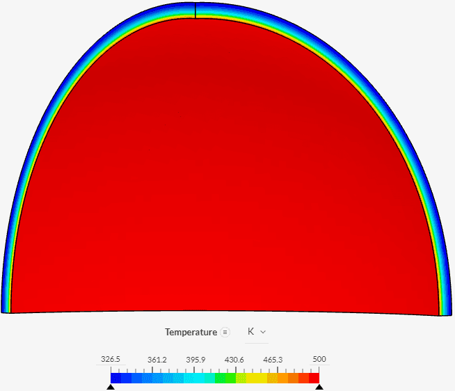
In Figure 4, we can see how temperature is changing in the sphere’s width, for the last time step:
Last updated: September 26th, 2025
Did this article solve your issue?
How can we do better?
We appreciate and value your feedback.


