
Most duct design software sizes ducts correctly and still lets a bad system through, because sizing to a friction rate says nothing about what the air does at the takeoff, the elbow, or the plenum. A ductulator gives you a diameter. It does not tell you that the branch three fittings downstream is starved because a mitered elbow is shedding a vortex across the inlet. That gap is where callbacks live: occupant complaints, whistling registers, fan power that never matches the schedule, and rebalancing after handover.
This article breaks the tool landscape into 5 categories, shows which engineering question each one answers, and covers where duct sizing stops and CFD starts.
What duct design software does
Duct design software converts a room-by-room load into a duct layout with sizes, then predicts the static pressure the fan has to overcome. Everything else is variation on that: some tools stop at a single duct segment, some carry a whole system, some draw it in 3D for fabrication, and some solve the airflow itself. Vendors label the same job differently, so duct software, ductwork software, duct designer, ducting design software, and ductwork design software all describe products from the categories below.
Four jobs sit inside that description, and almost no tool does all 4:
- Sizing. Pick a diameter or a rectangular equivalent for a target airflow, friction rate, or velocity.
- System pressure accounting. Add up straight-run friction and fitting losses along the critical path to get total external static pressure.
- Geometry and coordination. Draw the ductwork in 3D, route it around structure, and produce fabrication or BIM output.
- Flow prediction. Solve the actual 3D flow field to see velocity, pressure loss, recirculation, and noise sources in the real geometry.
Tools in the first 3 groups work from tabulated fitting losses. They assume your fittings behave like the ones in the table. Group 4 makes no such assumption, which is why it catches the problems the tables cannot describe.
Test your duct design before it gets fabricated
Import your duct CAD, run variants in parallel from the browser, and see pressure loss, recirculation, and flow split before anything reaches the shop.
The 5 categories of duct design software
Duct design software splits into 5 categories that answer different questions, and engineers usually need 2 or 3 of them rather than one tool that claims to do everything. Broader HVAC design software often bundles 2 or 3 of these categories into one license, which is worth checking before buying a second tool.
| Category | Question it answers | Representative tools | Where it fits |
|---|---|---|---|
| Duct sizing calculators and ductulators | What diameter carries this CFM at this friction rate? | ASHRAE duct calculator wheel, Elite Software Ductsize, Trane VariTrane Duct Designer, DuctChecker | First-pass sizing, field checks, sanity-checking someone else’s layout |
| Manual D residential design software | Does this residential system comply with ANSI/ACCA 1 Manual D? | ACCA-approved Manual D packages (Wrightsoft Right-Suite, Elite Software Rhvac, Adtek AccuDuct) | Permit sets, code compliance, load-to-duct workflows for houses |
| MEP CAD and BIM duct modeling | Does the ductwork fit and coordinate with structure and other trades? | Autodesk Revit MEP, AutoCAD MEP, ZWCAD | Commercial coordination, clash detection, drawing production |
| Fabrication and estimating | What sheet metal, fittings, and labor does this run need? | Contractor fabrication and estimating suites, h2x, Ductzone | Shop drawings, takeoffs, bids |
| CFD simulation platforms | What does the air actually do in this geometry? | SimScale, other CFD platforms | Non-standard fittings, plenums, industrial extraction, noise, pressure-loss validation |
None of these categories is a substitute for another. A Manual D package will not tell you why a plenum takeoff is starved. A CFD platform will not produce a permit-ready Manual D report. Pick per question.
Duct sizing calculators and ductulators
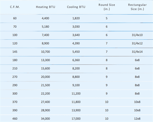
Duct sizing software solves one equation for one segment, and it is still the fastest way to get a defensible first pass. Give a ductulator or duct sizer airflow and a friction rate, and it returns a round diameter or a rectangular equivalent with the resulting velocity. Most also convert between round, rectangular, and flat oval.
Their limit is scope. A ductulator has no memory of the system, so it cannot tell you whether the cumulative loss along the critical path fits the fan’s available static pressure. That accounting is the next category’s job.
Manual D residential design software
Manual D software enforces the residential design sequence, which is the reason it exists. In the United States, the Air Conditioning Contractors of America publishes ANSI/ACCA 1 Manual D, currently the Third Edition (ANSI/ACCA 1 Manual D-2016), the ANSI-recognized standard for residential duct design. It specifies the design procedure, equivalent-length values for fittings, and the accepted range of duct construction materials, including expanded guidance on variable air volume (VAV) systems and on the effect of excess length, sag, and compression in flexible duct.
This is the category most residential HVAC design software falls into, and compliance output is the reason to buy it rather than a general sizing tool.
Manual D is the third step, not the first. Designers complete a room-by-room Manual J load calculation, then Manual S equipment selection, and only then size ducts to a friction rate derived from the selected blower’s available static pressure and the total effective length (TEL) of the critical path. Software that skips Manual J and asks you to type in a friction rate is doing arithmetic, not design.
MEP CAD and BIM duct modeling
HVAC CAD software answers the coordination question: will this ductwork physically fit, and does it clash with structure, cable tray, or sprinkler mains. These tools carry duct as parametric objects with sizes and connectors, which makes them the system of record for commercial drawing sets. Anything sold as 3D HVAC design software, HVAC drafting software, or duct drawing software sits here.
What they compute about airflow is usually a tabulated pressure-loss rollup. Useful for schedules. Not a prediction of the flow field.
Fabrication and estimating software
Fabrication software turns a design into sheet metal, fittings, hangers, and hours. It matters commercially and it constrains design, because a fitting that is cheap to draw and expensive to fabricate tends to get value-engineered into a mitered elbow on site.
That substitution is worth knowing about at design time, because it changes the pressure loss you accounted for.
CFD simulation platforms
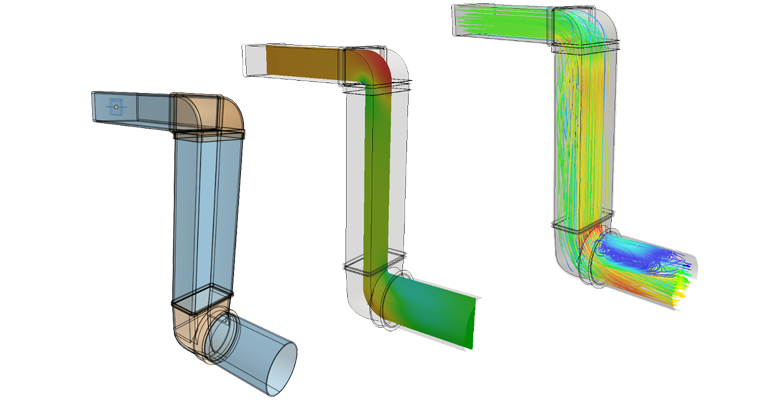
CFD solves the 3D flow field in your actual geometry, so it answers the questions the fitting tables cannot. Where a sizing tool applies an equivalent length to “elbow, 90 degrees, radius ratio 1.0,” CFD resolves the separation, the recirculation region, the velocity profile entering the next fitting, and the pressure loss that follows from all of it.
This is the category the other 4 hand off to when the geometry stops being standard. More on that below.
How to design an HVAC duct system
Air duct design runs in a fixed order: load, equipment, then ducts. Standards vary by country, and in the United States the ACCA sequence above is the reference for residential work. Commercial and industrial systems work from ASHRAE methods and project specifications instead, but the logical order is the same, and it holds whether you are doing AC duct design for a single house or a multi-zone commercial trunk.
The sequence in practice:
- Room-by-room load calculation. Sensible and latent load per room, not a whole-house number. Airflow per room follows from it.
- Equipment selection. Pick the unit, then read the blower table for available static pressure at the design airflow. That number is your entire pressure budget.
- Layout and total effective length. Route the ductwork, identify the critical path, and add measured length plus equivalent lengths for every fitting on it.
- Friction rate. Available static pressure divided by TEL, in inches of water column per 100 feet.
- Size every duct to that friction rate, then check velocity against noise limits.
- Validate the design where the geometry departs from the tables, and rebalance on paper rather than on site.
Step 6 is the one most workflows skip, and it is where a design either survives commissioning or generates a callback list.
If designed incorrectly, or without recurring evaluation during the design phase, the consequences include occupant discomfort, poor indoor air quality, high energy costs, and indoor noise. Designing a duct system means choosing the correct duct sizes and then testing the airflow within the system across multiple iterations.
Free and online duct design software: what you get and what you miss
Free duct design software covers sizing and simple system pressure well, and stops short of geometry-dependent behavior. That trade is worth understanding before it decides your workflow for you.
What free and browser-based tools reliably give you:
- Round, rectangular, and flat oval sizing at a chosen friction rate or velocity
- Round-to-rectangular equivalents
- Velocity checks against noise thresholds
- Fitting equivalent lengths from published tables
- Simple critical-path pressure totals
What they do not give you:
- Pressure loss for a fitting that is not in the table, which describes most plenums, transitions into equipment, and anything fabricated to fit a tight ceiling
- Flow split between branches when the takeoff sees a non-uniform inlet profile
- Recirculation and separation, the reason a duct can be correctly sized and still starve a branch
- Velocity fields that tell you where noise is generated
- Any way to compare 5 layout variants against each other on real numbers
Most free options are either a web ductulator or an HVAC duct design app on a phone, both of which are group-1 sizing tools with a nicer interface.
Browser-based CFD sits in a different place. You still run HVAC duct design online with no install and no HPC headaches, and you get the 3D flow field rather than a table lookup. SimScale runs entirely in the browser on a free Community plan for public projects, which makes online duct flow analysis available at the same friction as a web ductulator.
Run a duct flow analysis in your browser. Start free on SimScale.
Industrial and commercial duct design compared with residential
Industrial ductwork carries a harder set of constraints than residential, because the air itself can be the hazard. The ACCA sequence covers residential requirements and does not satisfy industrial duct design demands.
Compared with residential parameters, industrial ductwork systems have more specialized needs, since toxic air and safety hazards are present. Exposing workers to dust, fumes, vapors, and other occupational hazards causes serious health effects, including carbon monoxide poisoning. Pharmaceuticals, chemical processing, welding, and paint spraying all deal with this exhaust fume extraction problem directly, and capture velocity at the hood matters more than a friction rate along the trunk.
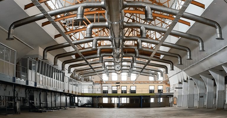
Commercial systems sit between the two. Loads are zoned, VAV boxes change the flow split at part load, and the ductwork has to coordinate with everything else above the ceiling, which is why commercial HVAC duct design is usually a coordination problem before it is a sizing problem. SimScale’s commercial ductwork design page covers that case in detail, including mechanical ventilation systems.
In all 3 settings the health and comfort of building occupants is the governing consideration. Fume extraction, ventilation, and duct runs have to be designed and signed off against regulation while still meeting efficiency targets. CFD is the tool that lets you test performance before anything is fabricated.
Where duct sizing stops and CFD begins
Duct sizing methods rely on tabulated fitting losses, so they lose accuracy exactly where geometry gets specific. Simplified analytical models were the only option for predicting flow profile and pressure drop, and with the complexity of modern industrial plants and tighter energy targets, those methods have reached their limits.
CFD gives three-dimensional insight into the whole flow field, accounting for all physical effects and the full duct geometry rather than a nearest-match table entry. Six cases where the difference shows up:
- Non-standard fittings. Mitered elbows, tight-radius transitions, and site-fabricated offsets that have no table entry.
- Plenums and equipment inlets. Where the flow profile entering a fan or coil determines its actual performance.
- Branch balancing. Flow splits at takeoffs with non-uniform inlet velocity, which is the usual cause of a starved branch on a correctly sized system.
- Noise sources. Velocity peaks and shear layers that generate the whistle a velocity check misses. See NVH simulation for the method.
- Industrial extraction. Capture efficiency at hoods and contaminant transport through the system.
- Pressure-loss validation. Confirming that total external static pressure matches what you accounted for, rather than discovering it at startup.
The physics underneath is standard: flow regime set by the Reynolds number, turbulent flow through nearly every duct at design velocity, and friction loss you can hand-calculate for straight runs using major head loss. CFD is how you get the same numbers for geometry the correlations do not cover. For the wider method, see computational methods for fluid dynamics in HVAC system design.
How to run a duct CFD analysis in the browser
Running HVAC duct design online through CFD takes 6 steps and no local install, and running variants in parallel means a comparison finishes in the time one run would take.
- Import the geometry. Upload the duct CAD from your MEP or mechanical tool. Interior flow volumes can be extracted rather than modeled separately.
- Choose the analysis type. Incompressible steady-state flow covers most HVAC duct work. Add heat transfer when duct gain or loss matters.
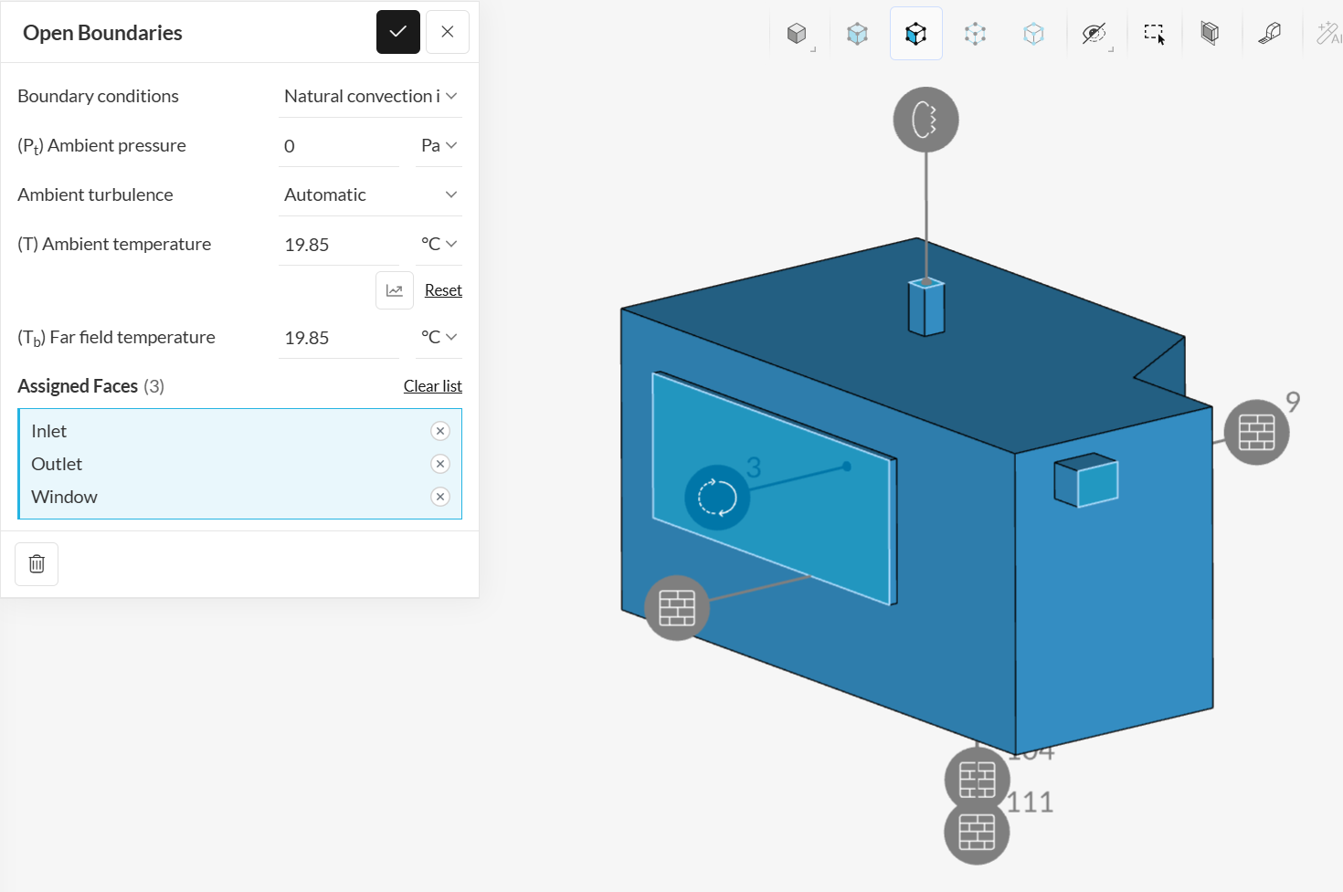
- Assign boundary conditions. Inlet volumetric flow rate or velocity, outlet pressure, and wall roughness matching the duct material.
- Mesh. Automatic meshing handles standard duct geometry. Refine near takeoffs, elbows, and dampers where gradients are steep.
- Run variants in parallel. Duplicate the simulation, change the fitting or the layout, and run them at the same time rather than in sequence.
- Read the results. Pressure drop across the run, velocity streamlines through fittings, recirculation regions, and flow split per branch.
Duct design simulation examples
Three SimScale examples cover the cases that duct sizing tools hand off: guide-vane placement, system pressure loss, and a client project that had to be quiet.
Turning vanes and recirculation: an inlet duct worked example
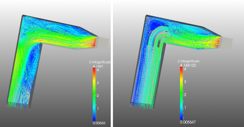
Turning vanes in a duct corner remove the recirculation region behind it and roughly double the usable width of the flow channel downstream. An inlet duct project run on SimScale shows the effect directly. The goal was a homogeneous flow field in front of a piece of plant equipment, because the installation geometry upstream was holding its performance back.
Two designs were compared on the velocity field through the mid-plane. In the design without vanes, a large recirculation region forms behind the corner and squeezes the effective flow channel to roughly half the duct width, so air leaves the outlet unevenly. With turning vanes added to the corner, the recirculation is gone and the outlet profile is close to uniform. Streamline plots make the mechanism obvious in a way a pressure-drop number never does.
A related HVAC simulation project runs the same question as a parametric study, comparing 1, 2, and 3 guide vanes in the critical section of a duct to find the arrangement that clears the recirculation without adding pressure loss you do not need.
Both cases land on the same point about tooling. A fitting table carries one equivalent length for “elbow with turning vanes”. It cannot tell you how many vanes to use, or where to put them.
Duct sizing project: HVAC pressure loss

This project predicts pressure loss in a duct design represented as a CAD model, then improves the design sequentially from the results. It is the workflow to copy when your total external static pressure needs to be defended rather than estimated.
Industrial ducting case study: Glanzner Dynamics
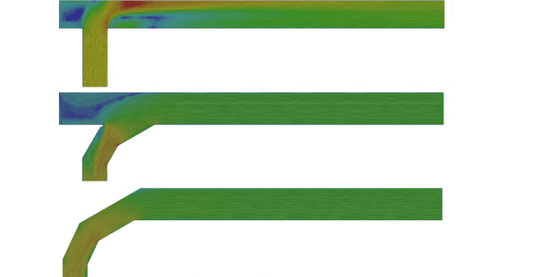
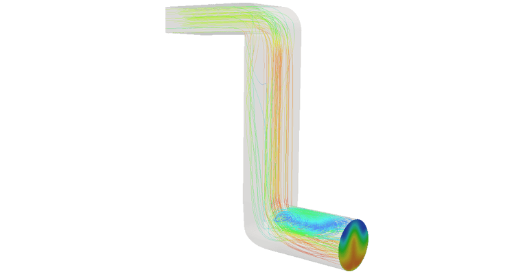
Glanzner Dynamics used SimScale to redesign an exhaust pipe for a ventilation system whose standard design was expected to generate noise from flow vortices. Streamlines from the first run showed vortices and a velocity increase immediately. Sebastian Glanzner then ran several design variants in parallel, landing on a curved pipe segment plus an air guide plate at a vane angle chosen from the results.

Sebastian Glanzner
Glanzner Dynamics

“With SimScale we achieved results very quickly and were able to improve the design of the pipe in less than a working day. Running multiple simulations simultaneously helped us speed up the process, and we had more time to complete the CAD drawings.”
How to choose duct design software
There is no single best duct design software, because the 5 categories answer different questions. Choose by the question you need answered, and expect to use 2 tools rather than one. The same applies to the wider question of the best HVAC design software: a package that wins on load calculation and drawing production will not be the one that predicts a flow field.
Six criteria worth checking before you commit:
- Compliance output. If you need a permit-ready Manual D report, confirm the package is on ACCA’s approved software list. No other capability substitutes for that.
- Where the pressure numbers come from. Tabulated equivalent lengths or a solved flow field. Both are valid, and they are not the same claim.
- Geometry fidelity. Whether the tool reads your actual CAD or asks you to re-enter the layout as a schematic.
- Parallel variants. Whether you can compare 5 layouts at once or have to run them one at a time. This decides how many options you actually test.
- Install and hardware. Browser-based tools remove the IT request and the workstation spec from the decision.
- Free tier scope. Free usually means limited scope, limited project privacy, or limited compute. Check which.
For HVAC work beyond ductwork, HVAC simulation software covers equipment, HVAC components, and whole-system ventilation system design.
Frequently asked questions
Most engineers use 2 tools: a sizing or Manual D package for compliance and first-pass sizing, and a CAD or BIM tool for coordination and drawings. Engineers working on non-standard geometry, industrial extraction, or noise add CFD to predict the flow field that the sizing tables cannot describe.
Yes. Free ductulators and browser-based sizing calculators cover round, rectangular, and flat oval sizing, velocity checks, and simple critical-path pressure totals. SimScale’s Community plan gives free browser-based CFD for public projects, which extends the free tier to actual flow prediction rather than table lookups.
Yes. Online duct design tools run in the browser, from sizing calculators through to full CFD platforms. SimScale runs CFD entirely in the browser with no install and no local hardware, so duct flow analysis works from any machine.
For residential compliance work, use a package on ACCA’s approved Manual D software list, since it produces the Manual J, Manual S, and Manual D outputs that permit reviewers accept. Add CFD when a specific run behaves in a way the equivalent-length tables do not explain.
Not for a standard residential system with catalog fittings, where Manual D methods are sufficient. CFD earns its place when geometry is non-standard, when a branch is starving on a correctly sized system, when noise is a design constraint, or when the ductwork carries contaminants.
CFD resolves the pressure loss that follows from the actual geometry rather than the nearest table entry, so accuracy is governed by mesh quality, turbulence model choice, and boundary conditions rather than by how closely your fitting matches a catalog part. Validate against a measured straight run first, then trust the fitting results.
ANSI/ACCA 1 Manual D is the ANSI-recognized US standard for residential duct system design, currently in its Third Edition (ANSI/ACCA 1 Manual D-2016). It specifies the design procedure, fitting equivalent lengths, duct construction materials, and guidance on VAV systems and flexible duct installation effects.
Test your duct design before it gets fabricated
Duct design software that sizes to a friction rate gets you a defensible layout. Simulating that layout tells you whether the air agrees.
SimScale is the AI-native cloud platform for engineering simulation, trusted by 800,000+ engineers worldwide. Import your duct CAD, run variants in parallel from the browser, and see pressure loss, recirculation, and flow split before anything reaches the shop.