Clean, uncontaminated air is an essential component of any industrial work environment. Exposing workers to dust, toxic fumes, vapors, and other occupational hazards can cause serious adverse health effects, such as carbon monoxide poisoning. Many industries are facing this fume extraction issue, including pharmaceuticals, chemical processing, welding, paint-spraying, and so on.
In order to maintain the health and well-being of the workers, it is critical that industrial ventilation and exhaust fume extraction systems are properly designed, constructed, and operated, and are in full compliance with the applicable requirements. One of the tools that can make this task easier is computational fluid dynamics, or CFD, which allows HVAC engineers to virtually test the performance of their industrial ventilation designs.
To illustrate how fluid flow simulation can help optimize HVAC system designs for exhaust fume extraction, SimScale hosted a short webinar. Watch the recording below:
Case Study: Fume Extraction System Design
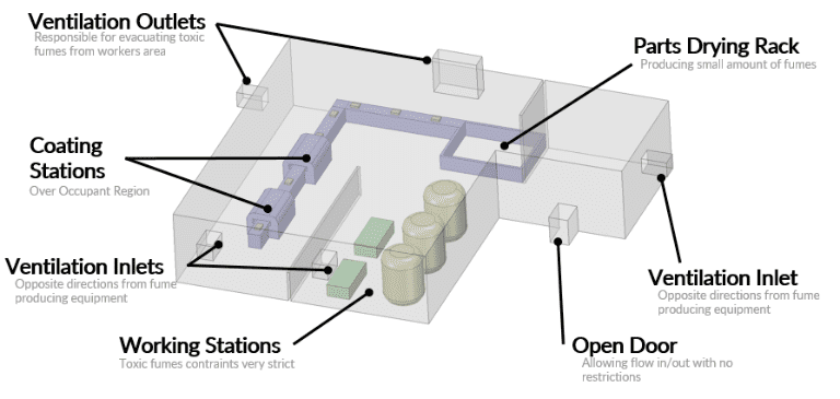
For the purpose of this case study, one of our customers agreed to share their successfully completed project. We have a large working space, with enclosed coating stations that produce toxic fumes and a small amount of fumes produced by the freshly coated parts. Our goal is to find the optimal inlet and outlet locations, as well as the total inlet and outlet mass flow.
Design 1: Fresh Air Supply from Top Inlets
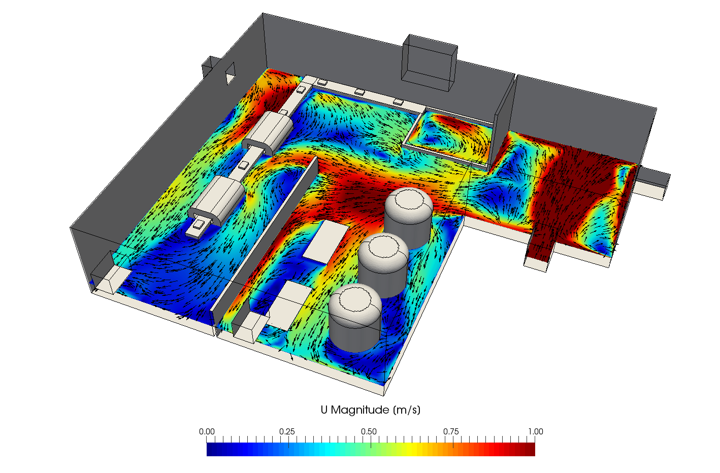
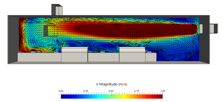
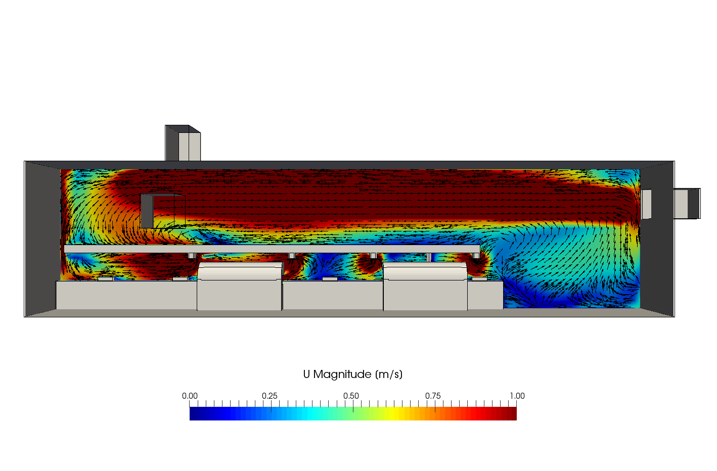
In a few easy steps, we upload the CAD model to the platform, set up the simulation and analyze the results. First of all, let’s take a look at the airflow velocity. We can see that in the first design configuration, the flow is oriented to keep fumes away from the working area. However, there are several problems, including the reversed flow behind coating area, as well as strong drafts which would create an uncomfortable environment for the workers.
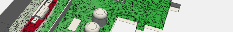
When we look at the results from a different angle, we can see the presence of flow recirculation between the coating stations, which reduces the exhaust fume extraction efficiency. A strong draft from the inlet fails to move the flow away from the coating stations.
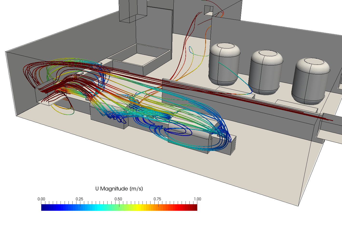
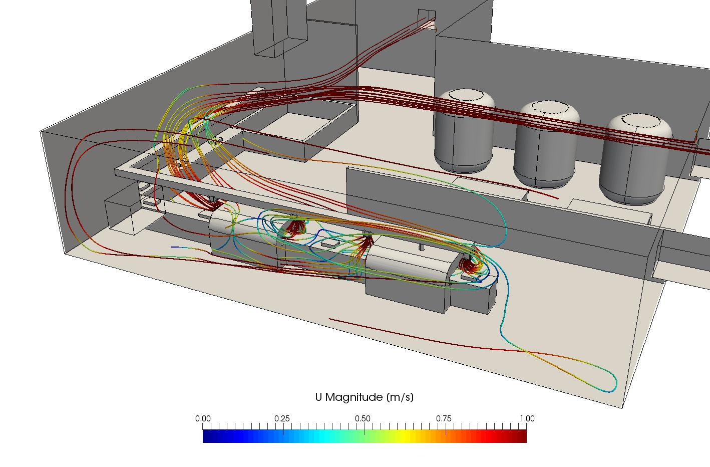
If we visualize the airflow using streamlines, we can see that the flow from the coating stations travels a long way before being extracted, mixing with the surrounding air, and the airflow patterns around the coating stations are erratic.
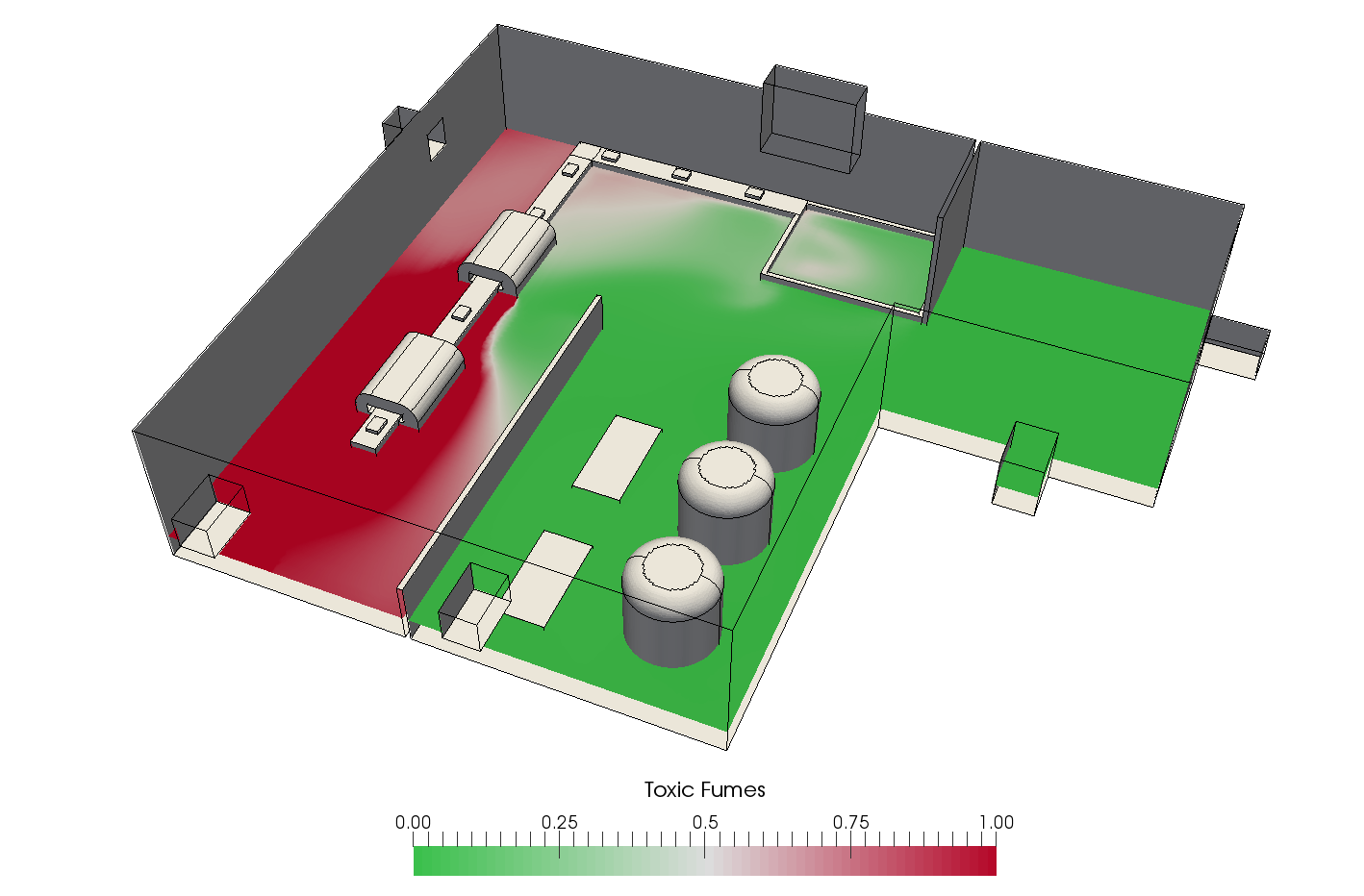
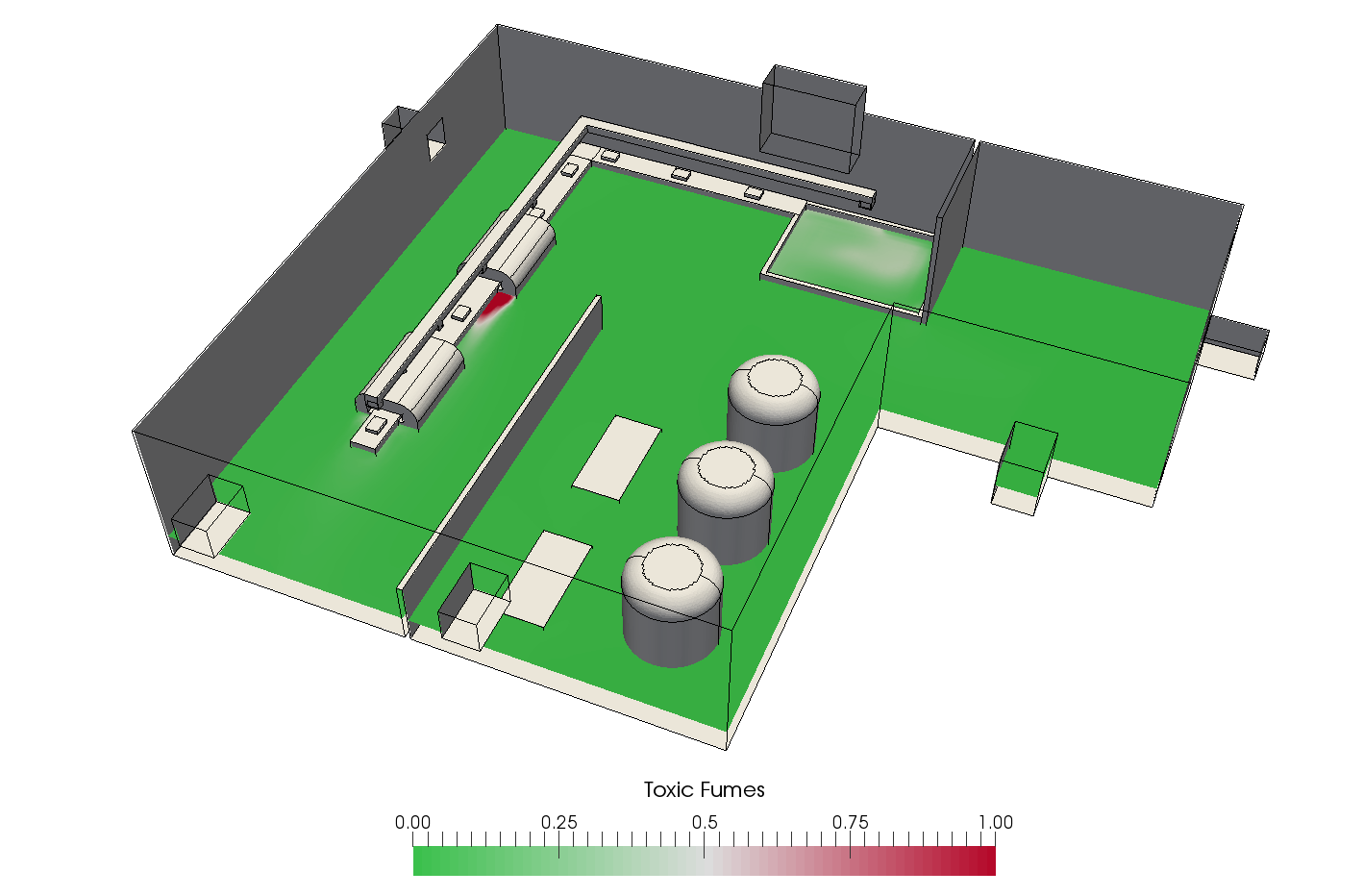
Now let’s look at the toxic exhaust fume distribution. The fumes were modeled as a passive scalar quantity. The ideal maximum concentration is c<0.25, while the safety limit with minimum respiratory gear is c<0.5.
We can immediately see a large red region with the concentration above the 0.5 limit (154m2). With the current ventilation system configuration, in a large section of the factory floor, the toxic fume concentration rises above the acceptable limit, even with security gear.
Now that we have identified the weak points of our original design (flow recirculation areas and fume concentration above the safety level), we need to find possible design modifications that would address those issues. One would be to increase the flow rate, which would increase the draft. However, this change would come with several adverse side effects. The energy consumption would increase, while the thermal comfort of the workers would deteriorate. We could also try to move the outlets and fume extractors closer to the coating stations. In this case study, we will investigate the impact of the latter solution.
Design 2: Layout Changes
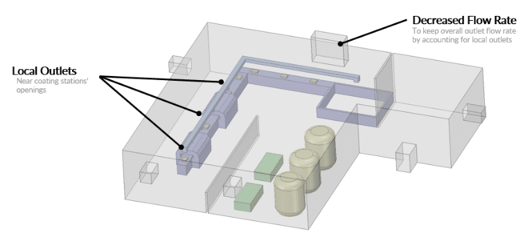
When we run the simulation for the new modified design, we can immediately observe strong drafts around the coating stations, which ensure the fumes get extracted. Local fume extractors diminish the impact of the reversed flow around the coating line.
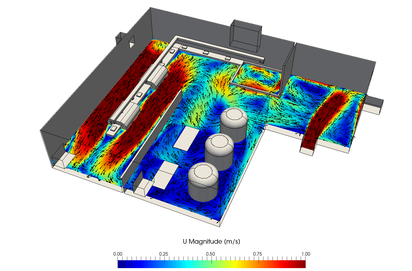
The local fume extraction outlets receive the flow from the coating station’s openings. We have also eliminated the recirculation below the inlet.
The flow from the coating stations gets extracted immediately and the flow patterns around the coating line are very straightforward.
If we look at the simulation results showing the toxic fume distribution, we can see that the region with the fume concentration above the safety limit has been virtually eliminated (reduced to 4m2). No significant fume concentration can be found throughout the working area. With the design changed, the toxic fumes were successfully contained around the coating stations. This design also eliminates the need for the workers to constantly wear the respiratory safety gear.
The whole simulation took less than two hours of manual time, five hours of computing time, and 150 core hours. Within that time, we were able to identify the possible design flaws in the original ventilation configuration and validate alternative industrial ventilation strategies to find the best solution. Since SimScale is a cloud-based platform, all we needed was a laptop with an Internet connection, and all the simulations were run directly in the web browser.
To learn more about this case study and see the SimScale platform in action, watch the recording of the webinar for free:
Read more articles like this by checking out our SimScale Blog here!


