In the early days of construction, wind tunnel tests were the standard method for investigating the indoor air quality (IAQ) of industrial and commercial buildings, hospitals or laboratories. With the advent of computer-aided engineering (CAE), advanced tools—particularly CFD—have become the principal method to quickly and effectively resolve these issues. CFD now plays an important role in accurately simulating the indoor airflow, helping building design engineers to improve the indoor air quality without compromising on low energy consumption.
Indoor Air Quality Why CFD?
In various heating, ventilation, and air conditioning (HVAC) systems, CFD can be used to determine which parameters will have the largest impact in relation to improving the IAQ, or indoor air quality, and living conditions. These parameters can include the thermal and ventilation simulation of the indoor systems. CFD facilitates the accurate simulation of various indoor models simply by changing the location of the heating or air conditioning units and diffuser types. This virtual design phase allows optimal conditions to be identified for a thermally comfortable, healthy, and energy efficient building before it gets to the construction phase. This reduces the cost and time required for the experimental testing, resulting in a more efficient design process and smarter decisions. [1]
Indoor Air Quality Sources of Contaminant Dispersion Affecting Indoor Air Quality (IAQ)
There are many sources of contaminant dispersion which can directly affect the IAQ. CFD simulations play a vital role in reducing the dispersion of contaminants in the indoor environment. The main sources are:
Contaminants
There are several contaminant sources that should be considered when analyzing the targeted zone. The common sources are [2]:
- Carbon dioxide (exhaled by-product of all mammalian metabolism)
- Carbon monoxide (tobacco smoking, incomplete combustion of hydrocarbons, and improperly ventilated heating or cooking appliances)
- Volatile organic compounds (VOC’s) (organic species from building material and finishes to cleaning agents and solvents)
Thermal Effects
The main heat sources or sinks in rooms include the following [2]:
- Transmission of heat by conduction through solid surfaces such as walls, ceiling, and floors
- Radiation between solid surfaces within the room
- Solar radiation through glazing
- Sensible and latent heat gains from occupants
- Heat gains from equipment, e.g., computers and lights
- Infiltration or air leakage
Wind and Infiltration
Small cracks around windows, walls or doors, can allow the air to leak, allowing infiltration into and out of the indoor space. This infiltration can have a drastic effect on heat loss, especially in the winter. These air leaks impact the flow pattern in the indoor space which in turn affects the contamination dispersion and overall IAQ.
Movement
Contaminant dispersion and indoor air quality are also affected by movement, for example:
- Movement of people
- Door opening
- Door swing pumping
Turbulence
As the characteristic Reynolds number of the flow increases, the flow does not remain streamline. Small fluctuations become amplified, creating unstable flow and finally becoming turbulent. In this situation, high mixing takes place, which enhances the dispersion effect of the contaminant.
Humidity
The difference in humidity levels leads to the change in density of the air. This, in turn, creates a significant buoyancy effect. As a result of this buoyancy, the circulation of the air inside can become more powerful, thus increasing the contaminant dispersion level and impacting the indoor air quality.
Download this case study for free to learn how the SimScale CFD platform was used to investigate a ducting system and optimize its performance.

Indoor Air Quality Characterization of Contaminant Distribution
There are several techniques to characterize the contaminant distribution. These techniques are taken into account when measuring the IAQ. The most commonly used ones are discussed below:
Contaminant Removal Effectiveness (CRE)
Contaminant removal effectiveness (CRE) can be used to assess the effectiveness of the ventilation system for an occupied zone. This parameter measures the effectiveness of the installed system in a particular zone to remove the existing contaminants. The formulation of CRE comes from the mean contaminant concentration at the supply and exhaust openings and the breathing zone [3]:
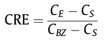 Where Ce and Cs are the contaminant concentrations at exhaust and source respectively, and Cbz is the contaminant concentration in the breathing zone (the mean value of occupied zone). The breathing zone is defined in ANSI/ASHRAE Standard 62.1 – 2004 [3]. The units of contaminant concentration are kg/m³, i.e., the mass of contaminant per unit volume of air. Sometimes contaminant concentration can also be represented by molar concentration, mass fraction, mole fraction, and parts per million (ppm).
CRE and CFD
There are several applications that can help optimize the flow conditions in order to maximize the contaminant removal efficiency ind improve indoor air quality. These applications are important to understand when considering contaminant removal effectiveness (CRE). Two of the examples show the CFD application is reducing the contaminant concentration in a hospital operating room [4] and a home kitchen [5].
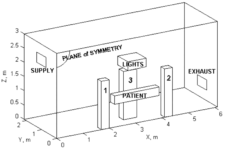
The figure on the left shows a hospital operating room where there are three operators and a patient. A light over a patient was also considered in this environment. The placement of the supply and exhaust was such that both are kept at a similar distance from the roof and floor respectively [4].
The main contaminant generator here is the patient. The study was performed to minimize the contaminant concentration in the operating room. The results below show a) contaminant concentration, b) temperature distribution, and c) relative humidity in the room [4].
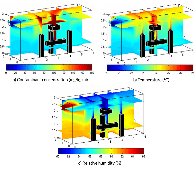 Within the areas of high and low temperature and humidity respectively, it can be observed that the value of contaminant concentration is high, for example, between the patient and the light and above the light. One can, therefore, resolve this problem by installing an extra exhaust just above the light in order to efficiently remove the contaminants.
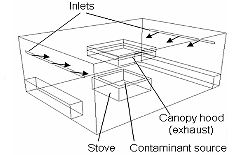
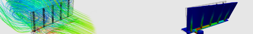
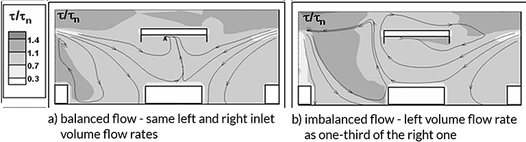
For the other application, the contaminant concentration in a home kitchen was studied. Here, the main source was the heated stove. The model used is shown in the figure on the left.
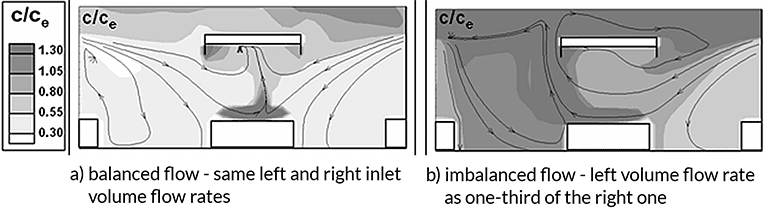
The two cases were simulated to study the CRE of the undertaken model: balanced flow—same left and right inlet volume flow rates; imbalanced flow—left volume flow rate as one-third of the right one. The results reveal an interesting contrast. A high concentration can be seen in the balanced case compared to the imbalanced one. This means that a considerably larger amount of contaminant escapes from the upper hood [5].
Local Mean Age of the Air (LMA):
Local mean age of the air (LMA) can be used to evaluate the efficiency of the ventilation system in relation to changing the old air to new. Thus, the lesser the age of air, the better the indoor air quality. The exact definition of the local mean age of the air can be expressed as [6] “the average time it takes for air to travel from the inlet to any point P in the room.” Using the decay method, the local mean age of the air can be calculated from [3]:
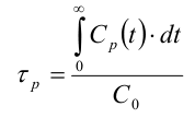 Where Cp(t) is the concentration of the contaminants at point p at time t, and C0 is the initial uniform concentration. Under fully mixed conditions, the local mean age of the year equals nominal time constant everywhere:
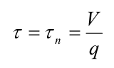 Where V and q are the volume of the room and volume flow rate respectively.
For CFD simulations, the LMA is calculated as a separate transport equation whose generic form looks like this:
![]() Where Г is diffusivity, which includes a molecular and turbulent contribution. Fluid particles entering the flow domain are typically assigned an initial age of zero, and the source term increases the age every second that fluid spends inside the domain.
Where Г is diffusivity, which includes a molecular and turbulent contribution. Fluid particles entering the flow domain are typically assigned an initial age of zero, and the source term increases the age every second that fluid spends inside the domain.
LMA and CFD
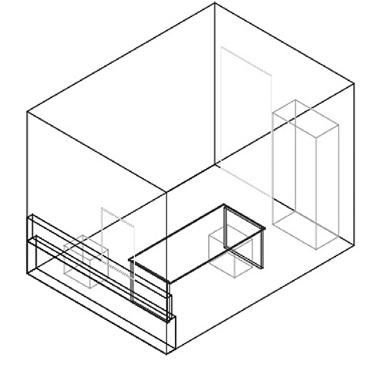
Local Mean Age (LMA) of the air can help to make sure that the availability of the fresh air in a domain is consistent. CFD allows the entire study to be done on a virtual model before the ventilation system is designed. One of the examples [7] shows the use of CFD for measuring the contaminant concentration in an office room in order to monitor the LMA.
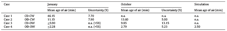
Four cases were tested:
- Case 1: both door and window closed
- Case 2: closed door and opened window
- Case 3: opened door and closed window
- Case 4: both door and window opened
The office model used is shown in the figure on the right.
The results in the table below clearly illustrate the effect that opening both door and window can have on the mean age of the air.
Similarly, in one of the studies, three different conceptual designs of the natural personalized ventilation (NPV) for a hospital room were proposed [8]; these are shown in the figure below.
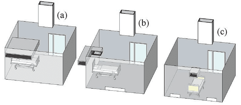
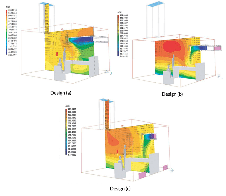
CFD simulations were carried out on all three designs to identify the optimal solution. The figures below reveal that the age of the air in design a is confined to a small packet area and above the large duct, whereas for design b, it is mostly near the ceiling over a larger area.
The most noticeable difference is the age of the air at bed level, which is nearly 305 s in the case of design a compared to design b, which has the value of 353 s. In this instance, designs a and b are identified as good choices.
Air Change Efficiency (ACE):
Another important parameter in monitoring the air change efficiency is air change efficiency (ACE). It is used to measure the effectiveness of the ventilation system in replacing the fresh air with old air. It is simply the ratio of the age of the air when it is completely mixed with the average time of replacement in the room [3]:
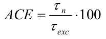 Where:
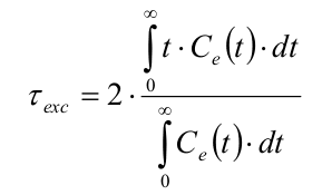 Where Ce(t) is the concentration inside the exhaust duct. The benefit of ACE is that the values can be compared to different rooms since they are normalized. 100%, 50%, and less than 50% all indicate a piston flow, fully mixed condition, and short-circuiting respectively.
SimScale’s CEO David Heiny tests the capabilities of the platform to solve a real-life engineering problem. Fill in the form and watch this free webinar to learn more!
ACE and CFD
The same example that was discussed in the section “contaminant removal effectiveness (CRE)” also shows the air change effectiveness (ACE) in a home kitchen [5]. The results below depict a very slight change of ACE and thus points to the fact that, in this case, CRE should be considered rather than ACE.
If you want to experiment with CFD and learn more about how to improve the IAQ, SimScale has a free community plan that you can use to test the platform. As SimScale is fully cloud-based, you only need a standard laptop or PC and an Internet connection to use it. Give it a try here.
References
- CFD in buildings, https://en.wikipedia.org/wiki/CFD_in_buildings
- Factors influencing the indoor transport of contaminants and modeling implications HSL/2006/29
- ANSI/ASHRAE Standard 62.1-2016, Ventilation for Acceptable Indoor Air Quality
- Ho, Son H., Luis Rosario, and Muhammad M. Rahman. Three-dimensional analysis for hospital operating room thermal comfort and contaminant removal. Applied Thermal Engineering 29.10 (2009): 2080-2092
- Novoselac, Atila, and Jelena Srebric. Comparison of air exchange efficiency and contaminant removal effectiveness as IAQ indices. TRANSACTIONS-AMERICAN SOCIETY OF HEATING REFRIGERATING AND AIR CONDITIONING ENGINEERS 109.2 (2003): 339-349
- Tommaso, R. M., E. Nino, and Giovanni Vincenzo Fracastoro. Influence of the boundary thermal conditions on the air change efficiency indexes. Indoor air 9.1 (1999): 63-69
- Buratti, C., R. Mariani, and E. Moretti. Mean age of air in a naturally ventilated office: Experimental data and simulations. Energy and Buildings 43.8 (2011): 2021-2027
- Adamu, Zulfikar A., Malcolm J. Cook, and Andrew DF Price. Natural Personalised Ventilation-A Novel Approach. International Journal of Ventilation 10.3 (2011): 263-275