HVAC systems are widely used in the automotive, construction, oil and gas, and aerospace industries. They consist of several cooling and heating components specifically designed to meet energy consumption requirements. In general, they are designed in an integrated form to efficiently manage and deliver energy in and out of the system. For example, automotive cooling packages including a radiator, condenser, and charge air cooler are designed to meet the requirements of an internal combustion engine.
Computational Methods Examples of CFD Analysis in HVAC System Design
Air conditioning systems, fans, and blowers are commonly installed in residential and commercial buildings to maximize thermal comfort. The overall operating efficiency of an HVAC system depends as much on proper design as on installation. In this article, I will briefly discuss my past experiences of using computational methods for fluid dynamics for different HVAC system design performance evaluations.
1. Automotive Cooling Systems
The high horsepower 15L diesel engine is known to produce an undesirable high-heat rejection rate. This is, in part, due to the necessity of meeting stringent emissions requirements. In order to meet airflow and top tank temperature requirements, vehicle front-end cooling packages must be properly sized, designed, and installed in high horsepower engines. In general, the larger the radiator size, the greater the restriction to the airflow. It is useful to evaluate pressure drop across the radiator component based on the given fin density at the early stage of the radiator design process.
This can be achieved using computational methods for fluid dynamics. The down-select of an optimized cooling package can be completed before being integrated into the vehicle’s system. Typical cooling packages also include a cooling fan which is crucial for delivering the ambient airflow when the vehicle is in parking or idling condition.
A CFD simulation can be performed under various fan speed conditions. In some cases, conjugate heat transfer is needed to accurately predict top tank temperature. In other cases, a cold flow CFD approach is sufficient to identify a system restriction curve. Cold flow, warm flow, and hot flow conditions are commonly used to simulate different driving conditions for cooling package design optimization.
2. Bladeless fans
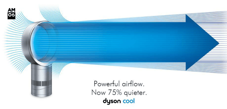
The bladeless fan designed by Dyson — named the “Dyson Air Multiplier”— is commonly considered to be a cost-effective and innovative cooling solution for household appliances. Computational methods for fluid dynamics are a powerful tool for evaluating the airflow performance of such unique design.
The RANS approach (Reynolds-averaged Navier-Stokes) is capable of predicting local airflow acceleration over a ramp hidden inside the plastic fan case. The hidden airflow acceleration inside the device enhances air momentum in conjunction with the mixing turbulence.
Air mass flow is further amplified when there is a high-speed flow in the internal ducting passage. In this scenario, there is no need to use blade anymore, eliminating the undesirable, non-uniform flow distribution that was previously found with the presence of conventional blades. With the bladeless configuration, uniform airflow distributions can easily be achieved, enhancing thermal comfort.
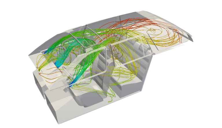
3. Blowers
HVAC blower noise has widely been recognized as an engineering challenge for the past few years. A typical HVAC system design in the automotive and aerospace industries consists of a blower and one ducting unit which assists in delivering air cooling flow to passengers. The system does this via different vents and registers near the passengers’ locations.
The blower needs to be properly designed to deliver sufficient mass flow rate and meet the thermal comfort requirements in the cabin, which, in the worst case scenarios, is exposed to solar radiation. High-speed blowers are desirable to meet such comfort requirements. However, the turbulence-associated noise generated by such high-speed moving blowers is undesirable, and such noise propagation frequencies are found to be within the human-perceived range and are disruptive to passengers.
Moreover, turbulence noise is found to be further enhanced inside non-uniform cross-sectional ducting systems where most of the airflow undergoes separation and reattachment multiple times depending on the ducting shape. The ducting shape is largely determined by the spacing limit and installation availability. Due to such complex flow structures formed inside the HVAC ducting system, the noise level of high-speed moving blowers is very difficult to be quantified for target setting.
At the early stage of the blower design process, the noise source can be evaluated using advanced computational methods for fluid dynamics. A nonlinear noise source can be calculated deterministically from a CFD analysis with advanced turbulence model implementation. Sound propagation can be evaluated with linear noise propagation code based on acoustics analogy formulation.
This combined coupling approach can be performed in a cost-effective manner for multiple design evaluations. The overall sound power level or sound pressure level (OASPL) based on a few selected microphone locations, can be quantified for acoustics performance comparison.
These are just a few of the applications of computational methods for fluid dynamics in the HVAC system design. If you would like to read about other applications or learn how to perform a CFD analysis to analyze and make changes to your HVAC system design, this page includes plenty of simulation templates, and there are a few recorded webinars. Remember that you can create a free SimScale community account.
Download this case study for free to learn how the SimScale CFD platform was used to investigate a ducting system and optimize its performance.