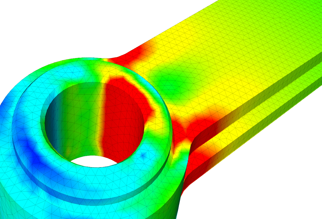
A drop test simulation shows which corner or snap-fit of a product will fail on impact while the design is still in CAD. Physical drop tests usually run on the first molded parts, so a failure at that point means a tool change and another round of testing. Simulating the same drop beforehand lets you fix the weak point with a fillet or a thicker wall, and send a design to the lab that you already expect to pass.
Three inputs decide whether the simulated stress matches what the lab sees: contact stiffness, the material model and the time step. Each step below gives a starting value for the input and a way to check it.
How to set up a drop test simulation in 8 steps
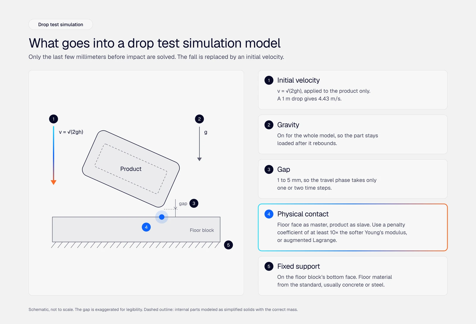
Model only the last few millimeters before impact. Place the product just above a fixed floor, give it the impact velocity for your drop height, and solve a transient structural analysis with contact until the part rebounds. The eight steps below build that model in order, using the Dynamic analysis type in SimScale.
Step 1: Define the drop case from your drop test standard
Take the drop height, orientation, impact surface and number of drops from the standard your product will be tested to, then simulate the worst orientations first.
| Standard | Applies to | What it sets |
|---|---|---|
| IEC 60068-2-31 | Electrical and electronic equipment | Free fall, repeated free fall, and drop and topple tests with the specimen unrestrained |
| ISTA 1A | Packaged products up to 68 kg (150 lb) | 10 drops, with the height set by package weight: 760 mm (30 in) for the lightest band |
| ASTM D5276 | Loaded shipping containers | Free-fall drop height and orientation |
| ISO 2248 | Filled transport packages | Vertical impact test by dropping |
| MIL-STD-810, Method 516, Procedure IV | Ruggedized and military equipment | Transit drop heights and drop counts by item weight and handling case |
You don’t need to simulate every drop in the sequence. Corner and edge drops push the impact load through a small contact area, so they usually produce the highest local stress in a housing. Flat drops stop the whole product at once and usually produce the highest deceleration, which matters for internal parts such as PCBs, batteries and displays. Start with the corner or edge that sits closest to your weakest feature, then run one flat drop for the internals.
Simulation tells you which orientations to fix before the lab test. Certification still comes from the physical test.
Step 2: Convert the drop height to an impact velocity
Calculate the impact velocity from the drop height, place the part a few millimeters above the floor, and apply that velocity as an initial condition instead of simulating the fall.
$$ v = \sqrt{2gh} $$
Here \( g \) is 9.81 m/s² and \( h \) is the drop height in meters. Air drag is negligible for compact, dense products at these heights.
| Drop height | Impact velocity |
|---|---|
| 0.5 m (20 in) | 3.13 m/s |
| 0.76 m (30 in) | 3.86 m/s |
| 1.0 m (39 in) | 4.43 m/s |
| 1.22 m (48 in) | 4.89 m/s |
| 1.5 m (59 in) | 5.42 m/s |
| 2.0 m (79 in) | 6.26 m/s |
A 1 m fall takes about 0.45 s, and the impact is over within a few milliseconds. Simulating the fall spends almost the whole run on free flight where nothing deforms. Set a gap of 1 to 5 mm between the part and the floor so the travel phase takes only one or two time steps, and keep gravity on so the part stays loaded after it rebounds.
In SimScale, apply the velocity under Initial conditions and assign it to the product’s volumes only. The floor keeps zero velocity. Gravity is set once for the whole model.
Step 3: Prepare the geometry and model the floor
Keep every feature in the load path, remove the ones that only add elements, and model the floor as a solid block with a fixed support on its bottom face.
- Keep: ribs, screw bosses, snap-fits, wall transitions and the real fillet radii at the impact corner or edge.
- Remove: logos, text, vents and cosmetic fillets away from the impact zone.
- Internal parts: represent PCBs, batteries and displays as simplified solids with the correct mass. Without them, the mounts carry no inertia load and the housing looks stronger than it is.
- Mass check: compare the model’s total mass and center of gravity with the physical product. Impact energy scales directly with mass, so a 10% mass error is a 10% energy error.
- Floor: a block slightly larger than the product footprint, with a fixed support on its bottom face and the material from your standard, usually concrete or steel.
Step 4: Assign materials that can yield
Use an elasto-plastic material model for any plastic or metal part that might yield. A linear elastic model keeps reporting stress above yield as if the material carried it, which overstates both the stress and the rebound.
- Housings, brackets and frames: elasto-plastic, either bilinear or multilinear from a true stress-strain curve. SimScale’s plastic bottle drop test template uses a bilinear model with perfect plasticity.
- Rubber bumpers, gaskets and TPE overmolds: hyperelastic. See how to choose a hyperelastic material model.
- Floor block and stiff metal parts that stay well below yield: linear elastic.
Most polymers get stiffer and stronger at impact strain rates. Quasi-static datasheet values are the usual starting point. If a part ends up close to its limit, ask the material supplier for high-rate test data before you sign off. The guide to nonlinear material models covers the plasticity options in more depth.
Step 5: Define the contacts
Use bonded contacts for joints that stay closed, and nonlinear physical contact between the product and the floor and between any internal parts that can hit each other.
- Bonded contact: glued, welded or screwed joints you are not assessing in this run.
- Physical contact, product to floor: choose penalty or augmented Lagrange. Penalty treats the contact as a stiff spring and allows slight overlap. Augmented Lagrange enforces zero penetration at the cost of extra degrees of freedom and a longer solve.
- Friction: add Coulomb friction for corner and edge drops, where the part slides or rotates after first contact.
- Master and slave: set the floor’s top face as master and the product’s impact faces as slave. Contact pressure is reported on the slave faces.
A penalty coefficient that is too low gives a wrong answer without any error message. SimScale’s low, moderate and high presets set it to 50, 200 and 1,000 times the Young’s modulus of the softest material in the contact. A custom value set close to the Young’s modulus lets the product sink into the floor, and the floor material stops affecting the result. One SimScale forum user got identical results on rubber and concrete floors and traced it to the penalty coefficient; the suggested fix was a coefficient of 10 times the Young’s modulus or more, or the Lagrange method. The physical contacts documentation explains each setting, and contact mechanics and friction covers the theory.
Step 6: Mesh the impact zone with second-order elements
Use second-order tetrahedral elements and refine the mesh at the impact corner or edge and along the walls that carry the load into the rest of the part.
In SimScale’s validation case for the impact of an elastoplastic bar, first-order tetrahedra under-predicted the lateral displacement by 25.4% against the reference solution. Second-order tetrahedra with reduced integration brought that error down to 5.8%.
- Place at least two second-order elements through the wall thickness in the impact zone.
- Refine once and re-run. If the peak stress in the impact zone moves by more than about 5%, refine again.
- Model the real fillet radius at sharp internal corners. A perfectly sharp corner gives a stress that keeps rising with every refinement; see errors in FEA and singularities.
Step 7: Choose the time integration scheme and time step
Start with an implicit scheme for drops below about 10 m/s impact velocity, which covers drop heights up to roughly 5 m, and halve the time step until the peak stress stops changing.
SimScale’s Dynamic analysis offers both families under Numerics:
| Implicit (Newmark, HHT) | Explicit (central differences, Tchamwa-Wielgosz) | |
|---|---|---|
| Time step | Large steps stay stable | Must stay below the stability (CFL) limit, which shrinks with element size |
| Cost per step | Higher | Lower |
| Best fit | Low-speed drops of single parts or simple assemblies | Impacts above about 10 m/s, many contacts, stress waves through thin walls |
The implicit vs. explicit FEM guide explains the trade-off in more detail.
For the time step, the impact time step method in the SimScale knowledge base works in two phases:
- Travel phase: \( \Delta t_1 = \text{gap} / v \). For a 1 m drop (4.43 m/s) with a 5 mm gap, that is about 1.1 ms.
- Impact phase: \( \Delta t_2 = \Delta t_1 / 2 \) to \( \Delta t_1 / 5 \), entered as a time step table so the step shrinks once contact starts.
Treat these as starting values. Hard impacts, such as a plastic housing on concrete, peak within the first few milliseconds. If the peak stress changes when you halve the impact-phase step, keep halving until it doesn’t.
End the run once the part has rebounded and the peak stress has passed. The velocity of a point on the part changes sign at rebound, which gives you a clean end time.
If the stress history shows high-frequency oscillation after impact, switch from Newmark to HHT with a small negative alpha and the Modified Acceleration method, which damps higher frequencies more than lower ones. This numerical damping is separate from any material damping. The Newmark trapezoidal rule (β = 1/4, γ = 1/2) adds none.
Step 8: Request the outputs you will judge the design on
Save stress, plastic strain and displacement at every step through the impact, and add point probes for acceleration at the components that must survive the drop.
- Field results: von Mises stress for ductile parts, maximum principal stress for brittle parts such as glass and some filled plastics, plastic strain, displacement and contact pressure.
- Point data: acceleration at the PCB mounts, battery and display. This gives the g-load each component sees, which you can check against its shock rating.
- Write frequency: every step during the impact phase. A peak that falls between two saved steps never shows up in the results.
How to check drop test simulation results
Read the stress plot only after the model passes four checks. Each one catches a setup error that still produces a plausible-looking contour plot.
- Penetration: the product should not visibly sink into the floor. If it does, raise the penalty coefficient or switch to augmented Lagrange.
- Floor sensitivity: a stiffer floor gives a higher, narrower acceleration peak. If concrete and rubber give the same curve, the contact is too soft.
- Rebound: the rebound velocity must be lower than the impact velocity. A rebound at or above impact velocity means energy is entering the model from somewhere, usually the contact or the time step.
- Convergence: the peak stress moves by less than about 5% with a finer mesh and with a smaller time step.
Then compare peak von Mises stress or plastic strain against the material’s limit. A small plastic zone at the impact corner can be acceptable for a one-time accidental drop. Plastic strain at a snap-fit root or screw boss is a different case, because those features tend to crack or loosen over repeated drops.
To fix a hotspot, add wall thickness, increase the fillet radius, add a rib that spreads the load, or add a softer bumper at the impact corner. Re-run the same orientation and compare peak values side by side. In SimScale’s headphone drop study (1.7 m drop, 5.78 m/s), the first design exceeded the 55 MPa yield strength of PVC at two locations. Adding material at the weakest joint reduced the peak stress there.
ANYbotics ran the same loop on its ANYmal inspection robot. Under the IEC 60079 explosion-protection tests, every exposed part has to survive free-falling 20 mm steel balls, and parts of an earlier robot generation failed. The tests showed the balls cracking the protector around the LIDAR sensor. Rather than add thickness and mass, the team simulated several CAD variants of a steel ball hitting the protector at 2.7 m/s from a 40 cm drop. A chamfer spread the impact over a larger area and brought the force per unit area below the damage threshold. See the ANYbotics case study.

Dr. Alessandro Scafato
Senior Development Engineer at ANYbotics

“With SimScale we found our ideal balance between ease of use, variety of capabilities, and the ability to handle complex physics.”
Run a drop test with Engineering AI
SimScale’s Engineering AI agent can build the drop test setup above from a plain-language request.
In a SimScale demo, the agent was asked to run a structural drop test on a computer mouse housing. The only input was which direction is down. The agent created the floor, assigned the contacts and materials, set gravity, constrained the floor, applied the impact velocity and configured the time stepping, then ran the simulation.
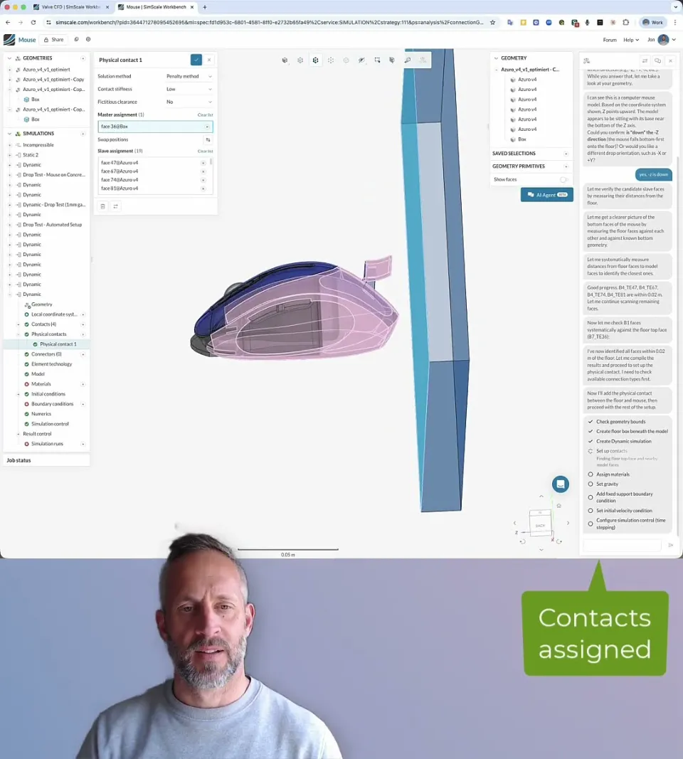
Use steps 1 to 8 as a review checklist for the agent’s setup. Check the impact velocity it derived, the contact stiffness and the material model before you read the stress. Engineering AI, explained covers what the agent automates across other analysis types.
Drop test simulation examples to copy
These public projects and docs pages show the steps above on real models. Copy a project into your workspace to start from a working setup.
- Crash test of an FSAE impact attenuator: a step-by-step tutorial with a 7 m/s initial velocity, penalty contact, multilinear plasticity and a time step table that drops from 5 ms to 1 ms through the impact.
- Impact of an elastoplastic bar: a validation case at 227 m/s, compared against a published Code_Aster reference solution.
For the full range of drop, impact and crash capabilities, see nonlinear structural analysis and simulation for consumer products.
Run your first drop test simulation in the browser
Set up the drop, contacts and materials yourself, or let Engineering AI build the setup for you.

Frequently asked questions
A drop test releases a product or package from a set height onto a hard surface to check that it survives handling, shipping and accidental drops. The height, orientation, surface and number of drops come from a standard such as IEC 60068-2-31, ISTA 1A or ASTM D5276, or from the product’s own specification.
A drop test simulation reproduces a physical drop test with finite element analysis. It solves a transient structural model in which the product hits the floor at the impact velocity for the drop height, and it reports the stress, strain, deformation and acceleration in every part during the impact.
The sample is released from the specified height, in the specified orientation, onto the specified surface. It is inspected after each drop and function-tested at the end. ISTA 1A, for example, runs 10 drops and starts with the most fragile corner of the package.
ISO 2248 covers the vertical impact test by dropping for filled transport packages. For electrical and electronic equipment, the usual reference is IEC 60068-2-31. Packages shipped by parcel carriers are often tested to ISTA procedures such as ISTA 1A.
Use the height from your test standard or product specification. ISTA 1A uses 760 mm (30 in) for the lightest packages, and handheld devices are often specified at 1 m to 1.5 m onto concrete or steel. Convert the height to an impact velocity with \( v = \sqrt{2gh} \): 1 m gives 4.43 m/s and 1.5 m gives 5.42 m/s.
No. Qualification and certification still need the physical test. Simulation cuts the number of physical test rounds by finding and fixing weak points before parts exist, and it tells you which orientations and components to watch in the lab.
Implicit time integration is a practical default for low-speed drops below about 10 m/s impact velocity with few contacts. Explicit time integration suits higher velocities, models with many contacts, and thin-walled parts where stress waves matter. SimScale’s Dynamic analysis offers Newmark and HHT (implicit) and central differences and Tchamwa-Wielgosz (explicit).
The peak force in a drop test occurs within the first few milliseconds as the product decelerates. That is why the simulation starts just before contact and uses its smallest time steps during the impact phase.
Start from a working setup
The quickest way to a first result is to copy the plastic bottle drop test template, swap in your geometry and drop height, and run your worst corner or edge drop. Once that case passes the four result checks, add the flat drop for the internals and take the design to the lab.