In general, we can decompose errors in FEA—finite element analysis—in three main groups:
- Modeling errors due to simplifications (“We try to model the real world yet are not able to do it 100%.”)
- Discretization errors that arise from the creation of the mesh
- Numerical errors of the solution of the FEA equations
Furthermore, it must be kept in mind that the finite element method, in addition to the other numerical methods (FVM, FDM, BEM) consists of approximations.
FEA Errors Modeling Errors in FEA
The finite element description is a boundary value problem (BVP), which means there is a differential equation with a number of constraints called boundary conditions.
The solution to a BVP must resolve the differential equation and satisfy the boundary condition (which I will elaborate in more detail in another article).1
Errors of this type can include:
• the wrong geometric description: for instance, we use axial symmetry or rotational symmetry, but often forget that we are dealing with an antisymmetric load
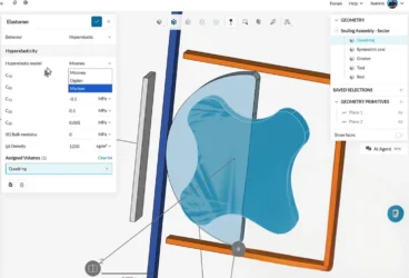
• the wrong definition of the material: for example, the limit of Poisson’s ratio in isotropic materials
• the wrong definition of the load: trying to simplify complex load states or a number of loads with one load (depends on the case). But often “the difference between the effects of two different but statically equivalent loads becomes very small at sufficiently large distances from load” as Saint-Venant’s Principle expresses
• the wrong boundary conditions: if you forget to fix model (rigid body motion) or set boundary conditions, you might inadvertently falsify the results
• the wrong type of analysis
Concerning the analysis types, there are several options:
- Is there a material linearity or nonlinearity?
- Is there a geometric linearity or nonlinearity? Large deformation or strains?
- In relation to contact definition, is it with friction or without friction? Master-Slave definition? (For a deeper understanding of Master-Slave definitions, see this topic.)
- Does buckling occur?
- Is the problem time-dependent or is it in the steady state, meaning a quasi-static behavior can be assumed?
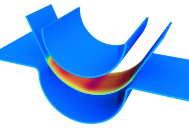
The purpose of a helmet is to protect the person who wears it from a head injury during impact. In this project, the impact of a human skull with and without a helmet was simulated with a nonlinear dynamic analysis. Download this case study for free.

Introduction to Singularities Small Excursus to Singularities
A finite element model will sometimes contain a so-called singularity. This means there are points in your model where values tend toward an infinite value.4
If you are a newbie to finite element analysis, you might assume that a singularity is a term derived from a science-fiction movie like Star Trek.
The image below shows you what a singularity is:5
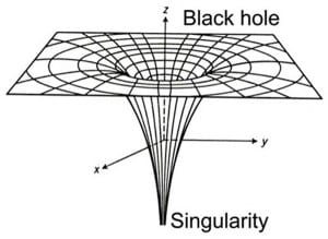
A singularity, as shown in the picture above, is basically the same in your FEA model. For example, in both cases, the infinite density and gravity are equivalent to an infinite stress at a sharp corner.
Singularities can be confusing because they cause an accuracy problem inside the model, which implies a problem with visualization because singularities extend the range of the stresses. This means that smaller stresses can appear to be negligible.
But what causes singularities? If you some online research, you will find a multitude of causes and explanations. However, summa summarum, we can confidently identify boundary conditions as the major cause.
Another predestinated problem implies that singularity problems are cracks because they can be seen as a 180° re-entrant corner. Luckily, the crack tip does not have to be studied every time, rather the focus can be placed on the stress intensity factor, using the J-Integral, or even looking at the energy dissipated during fracture (strain energy release rate).
Additionally, it is important to pay attention if you apply a force to a single node. This will give you infinite stresses! In the real world, forces are never applied on a single node due to the Saint-Venant’s principle, which tells us that “the difference between the effects of two different but statically equivalent loads becomes very small at sufficiently large distances from the load.” I also encountered this problem when I modeled a Hertzian contact in ANSYS and applied my force to a single node on the top of my cylinder. It took me two days to realize my mistake.

Types of Errors in FEA Discretization Errors
- Which type of elements should be used? If we are in 2D, should we use plane stress or plane strain?
- Which mesh density is accurate enough to yield a good solution without investing an immense amount of time? Always start with a coarse mesh. By starting with a coarse mesh, the time and accuracy can be monitored and adjusted with an increase in the mesh fineness.
- Which element order should I use? In SimScale, you have two possibilities:
- First-order tetrahedral elements
- Second-order tetrahedral elements

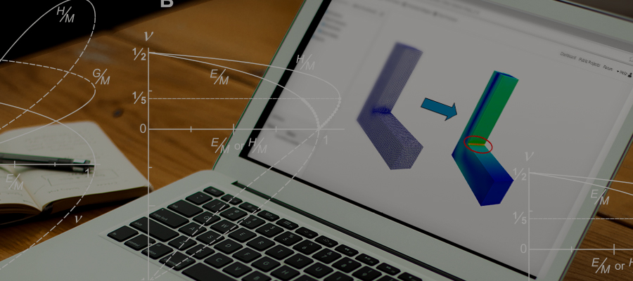
Second-order elements can assume either a concave or convex shape, meaning that they can display better results and deformation by easily mapping to curvilinear geometry. This is a big advantage when handling nonlinear material, i.e., elastoplastic or hyperelastic material. But everything comes at a price. The computational effort and time consumption are higher than using first-order tetrahedral elements.
Mesh Refinement Methods
h-method: reducing the size of the mesh
p-method: increase of the polynomial order in the element, which is good for regions with a low-stress gradient
r-method: relocates the position of a node
or combinations of the methods mentioned: hr, which is good for regions with large stress gradients, and hp or hpr
A nice mnemonic for these methods:
h-method = MesH
p-method = Polynomial order
r-method = Relocate node
General warnings to avoid errors in FEA:
- Check that your software is operating with the values you typed in!
- Look at the deformed shape in the post-processing part of your simulation and check if the result is roughly what you expected.

Types of Errors in FEA Numerical Errors
- Integration errors in FEA caused by Gauss integration lead to numerical instabilities. However, a large number of Gauss points is far too expensive. For the basic concept of Gauss Quadrature, see: Excursus – FEM – Gauss Quadrature
Useful information: Exact integrations provide a structure that is too stiff!2
- Rounding errors in FEA can be caused by adding or subtracting very large and very small numbers, or when dividing by small numbers.
- Matrix conditioning errors3
Conclusion Practice Makes Perfect!
“Science walks forward on two feet, namely theory and experiment… but continuous progress is only made by the use of both.” – Robert A. Millikan
I hope this article gave you some useful tips on how to avoid errors in FEA and better understand singularities. If you’d like to learn more about the SimScale cloud-based simulation platform and its features, download this overview.
Alternatively, watch the recording of our “More Durable Consumer Products with FEA” webinar. All you need to do is fill out this short form and it will play automatically.
References
- Wikipedia–Boundary value problem (https://en.wikipedia.org/wiki/Boundary_value_problem)
- Introduction to the Finite Element Method–Niels Ottosen & Hans Petersson-Chapter 20.3
- https://nm.mathforcollege.com/mws/gen/04sle/mws_gen_sle_spe_adequacy.pdf
- https://www.comsol.com/blogs/singularities-in-finite-element-models-dealing-with-red-spots/
- https://www.physicsoftheuniverse.com/topics_blackholes_singularities.html
- https://www.me.mtu.edu/~mavable/MEEM4405/Modeling.pdf
- https://forum.simscale.com/t/when-should-i-use-a-second-order-mesh/25899