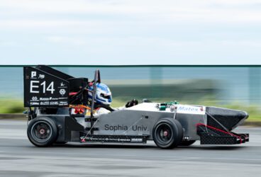
Cardiff Racing is Cardiff University’s Formula Student team, attending the UK event every year as well as other similar competitions across Europe. The team has seen great success and continues to design, simulate, innovate and learn in the atmosphere of competition with SimScale. The concept for Cardiff Racing’s fifteenth car, CR15, was to replace the hybrid monocoque (front) and steel space frame (rear) with a full monocoque chassis design. This new design would reduce engine swap times, increase the accuracy of suspension hardpoints, reduce the chassis manufacturing time, and increase torsional stiffness. The major chassis concept change unlocked new design possibilities and challenges across the other design areas.
![]()
One of these design areas was aerodynamics, which took advantage of the new chassis by producing a completely new aerodynamic package. According to the team, SimScale was chosen to undertake the computational fluid dynamics (CFD) analysis, due to the quick solving times, ability to work on a computer anywhere, the wealth of tutorials, helpful forum posts, and attentive team of engineers to ensure the models were working correctly.
One disadvantage of the enclosed chassis design was the lack of ventilation to the engine bay, which could cause the engine to overheat. Due to this, so suitable cooling measures had to be achieved to ensure reliability. This consideration was a key design factor when conceptualizing and designing the new aerodynamic package.
The first front wing designed for the CR15 was a 3-stage wing on each side of the car (comprised of a 400mm main plane and two 100mm high lift elements) to produce downforce and move air over the front wheel, reducing the front wheel drag and turbulent wake effects. This design worked well, but produced minimal flow along the side of the car where the radiators were mounted, reducing the cooling effect needed. The radiator position could not be altered, as they were located at the longitudinal center of gravity as low down as possible to reduce roll inertia. This meant a flow altering element needed to be added to the front wing to move more air to the radiators.
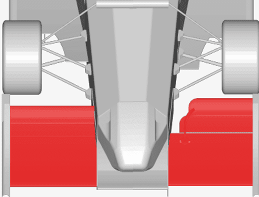
The fast full-car simulation with SimScale allowed many design versions to be modeled, tested, analyzed and refined until the final design was chosen. Based primarily on the Y250 elements of an F1 front wing, the upper wing elements end in a point producing a vortex, which controls the flow to the floor and separates the flow of turbulent air from the tires away from the rest of the car.
On the CR15 model, the elements allow the high-pressure air to spill over into the lower pressure underneath, moving the air down and horizontal rather than up over the top of the rad ducts. This flow then runs down the side of the car to feed the radiators; a side effect is that some of the flow is directed under the car feeding more air into the diffuser. The performance improvements of this implementation were 6x the air flowing through the radiators and a 7% increase in overall downforce primarily from the diffuser.
The effects of the ‘Y250’ were inspected by Cardiff Racing team using the inbuilt solution field. The following images outline the effect the two front wing designs have.
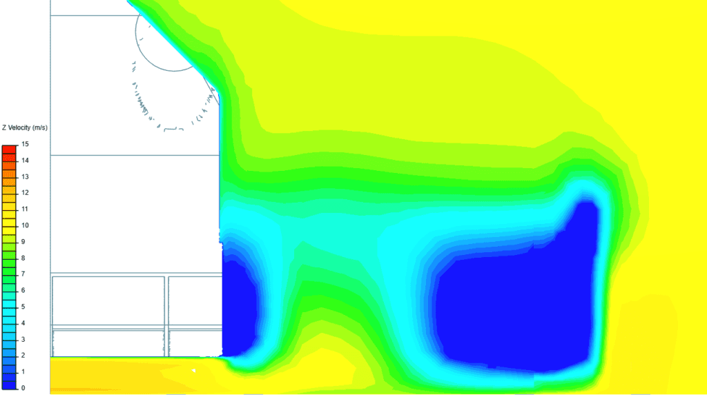
Figure 4 shows a top-down velocity cut plane, the inlet velocity being 10m/s. Comparing the velocities of both images, more air is flowing along the side of the chassis in the top “Y250” section.
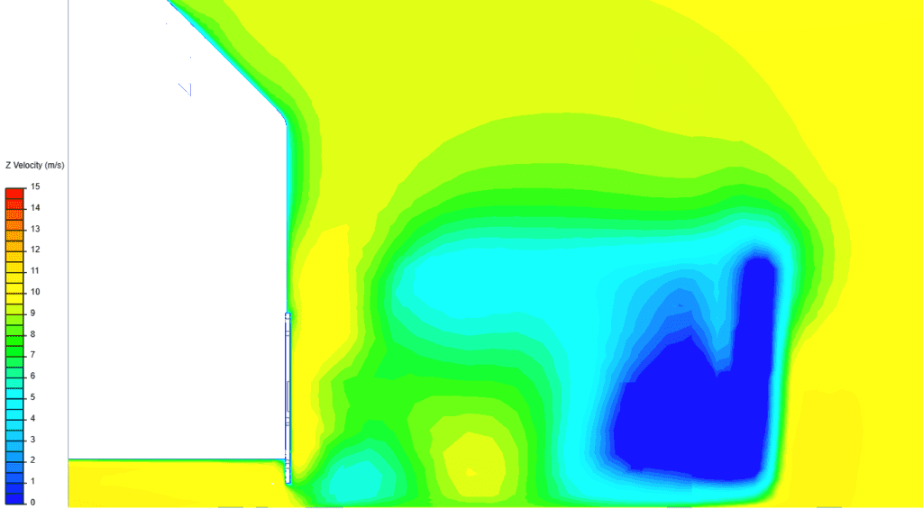
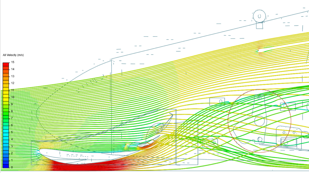
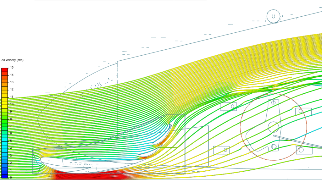
Similarly, the longitudinal flow with a front cutting plane between the front wishbones is shown in Figure 5. The introduction of the front wing “Y250” element has removed the low-velocity region near the chassis.
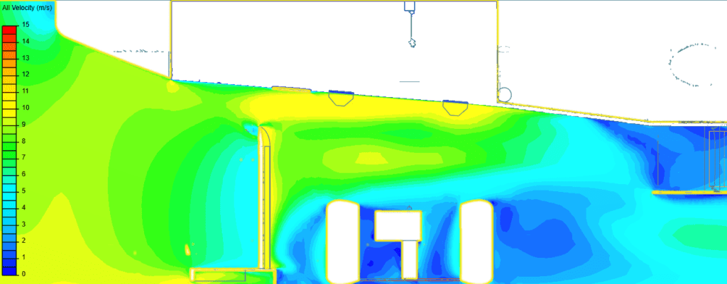
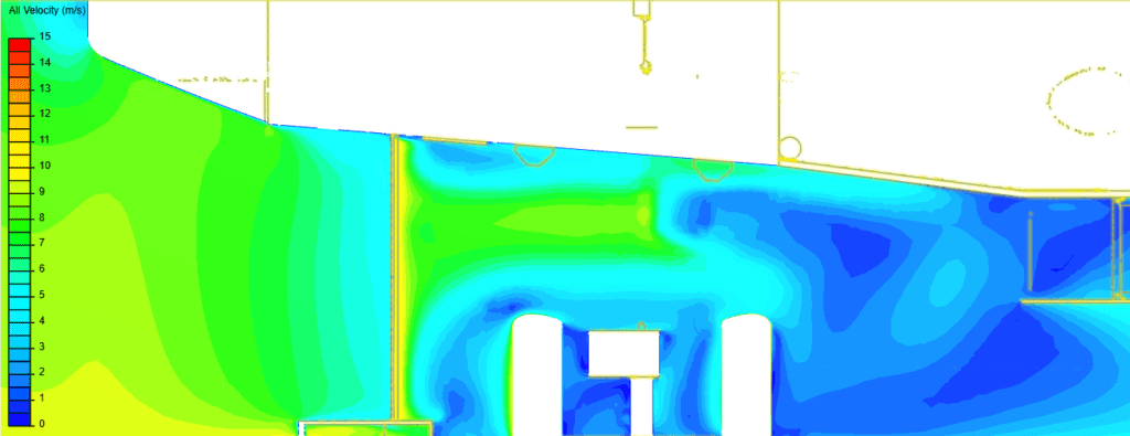
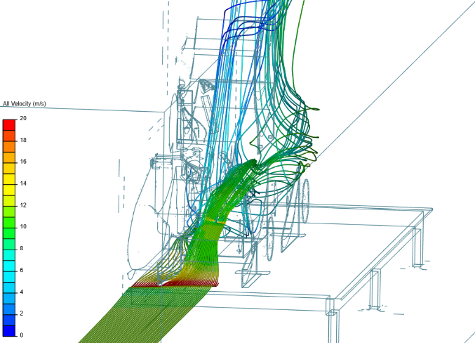
Figure 6 shows exactly how the element works to direct the flow; spiraling the flow from the top of the wing over into the low pressure underside, then flowing along and towards the floor.
The main advantage of SimScale is the cloud-based functionality where the simulations are run on dedicated high-powered servers allowing for quicker solving. This has given the team this year the ability to run many simulations at the same time or in quick succession to optimize the designs as much as possible in the limited time available. Compared to the previous CFD package used, they have been able to increase the complexity of the CAD model, adding in suspension members, uprights, engine air intake, and exhaust. The Formula Student tutorials provided by the SimScale Academy allowed the team to produce accurate yet core hour-efficient simulations, taking advantage of all the tools within SimScale to simulate rotating wheels, wheels spoke porosity, and radiator porosity, enabling the Cardiff Racing team to understand in even more detail how the aero package performs in real-life.
To ensure that the simulations were accurate, Cardiff Racing compared the simulated results with results gained via wind tunnel testing. The wind tunnel used at The University of the West of England could read the corner weight and drag of the car with stationary floor and wheels, which was not ideal for understanding the dynamic effects. The downforce and drag values measured differed by -5.85 % and +3.17 % in downforce and drag respectively, therefore it was concluded that this was an acceptable error.
If your team is interested in an academic sponsorship to enhance the performance of your vehicle, no matter if it is in Formula Student or any other competition that we sponsor, make sure to check out the Academic Plan.