Challenges
Results
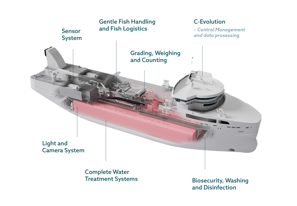
Cflow designs and builds fish handling systems for the aquaculture and fisheries industries. From its base in Langevåg on the west coast of Norway, the company has spent 24 years developing equipment for the gentle handling of live fish across the entire value chain: crowding, pumping, sorting, water separation, treatment, cooling, transport, and the loading and unloading of well boats. Systems are engineered to a customer’s vessel and operation, so each program brings its own geometry and space constraints.
Onur Aydemir is a Mechanical Design Engineer at Cflow. A marine engineer with five years of field experience, he specializes in hydrodynamic and dynamic analysis, the stochastic characterization of environmental conditions, and the modeling of fluid behavior inside and around structures, applied to the design of marine facilities and vessels.
From Experience-Led Concepts to Validated Geometry: Cflow’s Adoption of SimScale
Cflow’s products are flow machines that carry live animals, and their performance is set by internal hydrodynamics that cannot easily be observed or measured from outside the component. Historically, concepts for equipment like this were selected on the strength of previous projects on comparable vessels and the accumulated experience of the engineering team. The company turned to 3D CFD simulation to get a better understanding of product performance, and to drive continual improvements to performance and quality.
Initially, this was done by outsourcing simulation work to external service providers, but Cflow made the decision to bring simulation in-house, seeking to get simulation insights earlier in the design process. As Onur remarks: “to truly drive design direction, the simulation needs to happen while the concept design is still a concept”.
Working on that basis, Onur starts simulation work as soon as the initial designs are complete – validating whether it meets Cflow’s requirements and the customer’s. If performance falls short, he manipulates the geometry, recalculates, and iterates until the flow sits inside acceptable boundaries. Only then does the project move on to the solid model and the drawings. He says: “Without simulation it would be impossible to meaningfully compare two designs and decide which is best. With SimScale I can make that decision very quickly and move on.”
The economic benefits of doing that in-house are compelling. “For the same cost, you can test ten cases with our SimScale subscription instead of one case with a consultancy,” Onur says. Having the freedom to explore so many more design options, early in the design cycle, translates into savings in both cost and time for Cflow.
Onur Aydemir
Mechanical Design Engineer, Cflow

“SimScale strengthens our hand and gives us confidence in our products when we deliver them to the customer. It strengthens our decision-making process and reduces the time it takes to decide what we are going to do.”
Working on a single platform also gives Cflow room to grow the scope of its analysis. Their SimScale subscription also covers structural mechanics, important for products that are simultaneously flow devices and marine structures exposed to vessel motion and sea loads.
CFD: A Vacuum Inlet That Protects Live Salmon
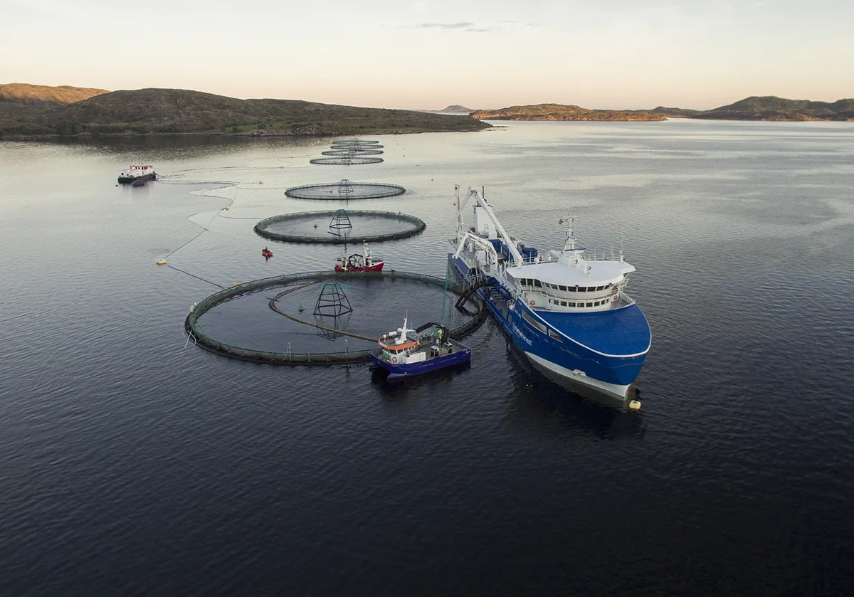
Cflow’s fish transfer equipment uses a hose/piping system and vacuum chamber to transfer live fish from sea-based cages into a well boat’s cargo hold for treatment or harvesting. This is a journey that a single fish will make multiple times over its lifetime, requiring regular de-lousing to guard against disease, so the welfare of the fish during the transfer process is critical.
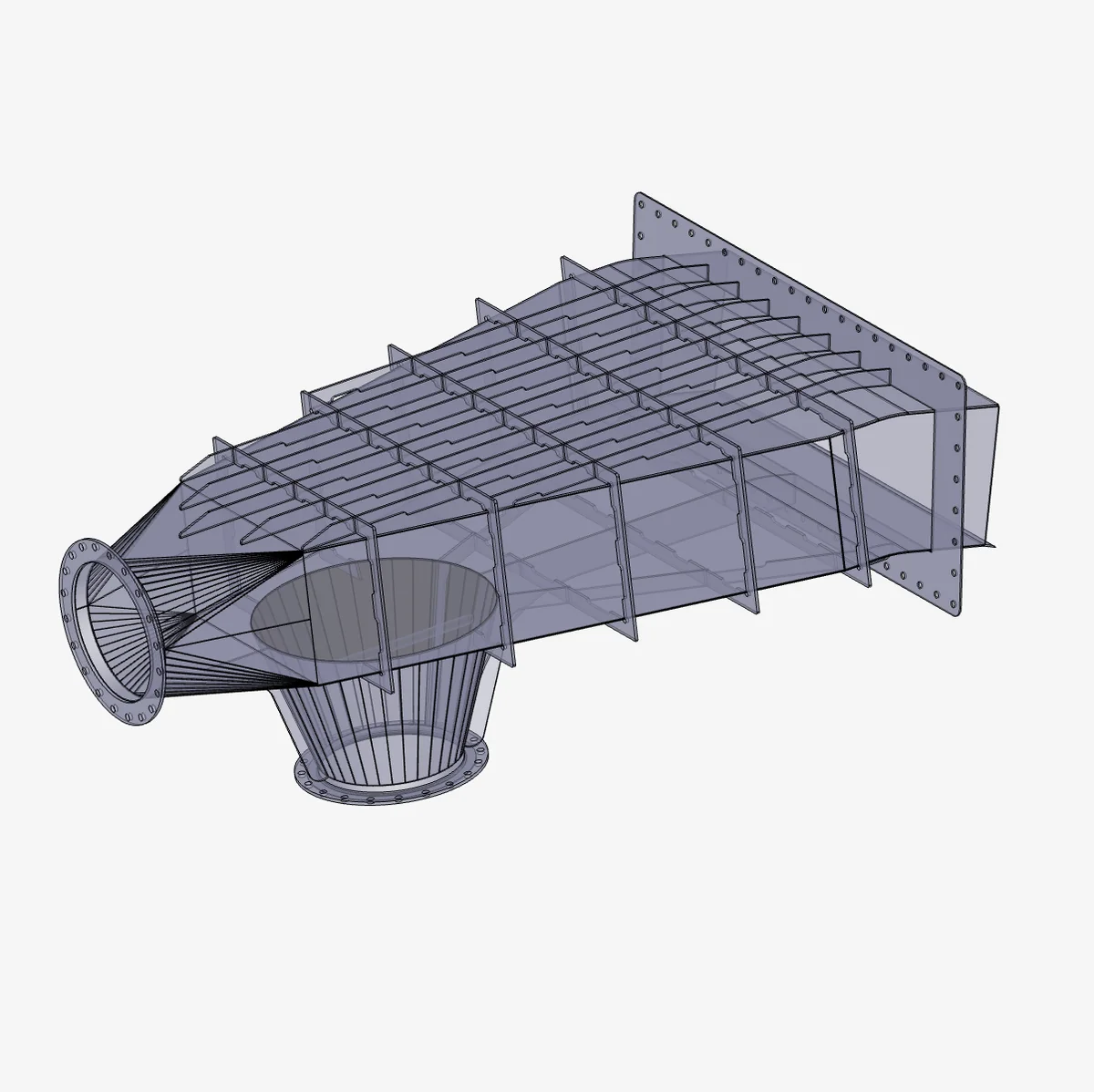
That journey runs through flexible hoses from the sea cage into the well boat and through the vacuum chamber. The component at the top of that path is the vacuum inlet chute, and its job is to provide a controlled transition from the inlet flow into the water-separation and cargo-hold system, allowing the flow to expand and decelerate gradually before it reaches the water separator and the cargo hold below.
The geometry of this diffuser is an important part of the design and may need to be varied from one vessel to the next, with each installation having different deck-space constraints and different upstream and downstream flow paths.
Why Smooth Flow Matters
Getting the design right is essential for fish welfare, and ultimately also the quality of harvested fish. As Onur puts it, “each fish is very valuable, so as a farm owner you want to handle them as carefully as possible.”
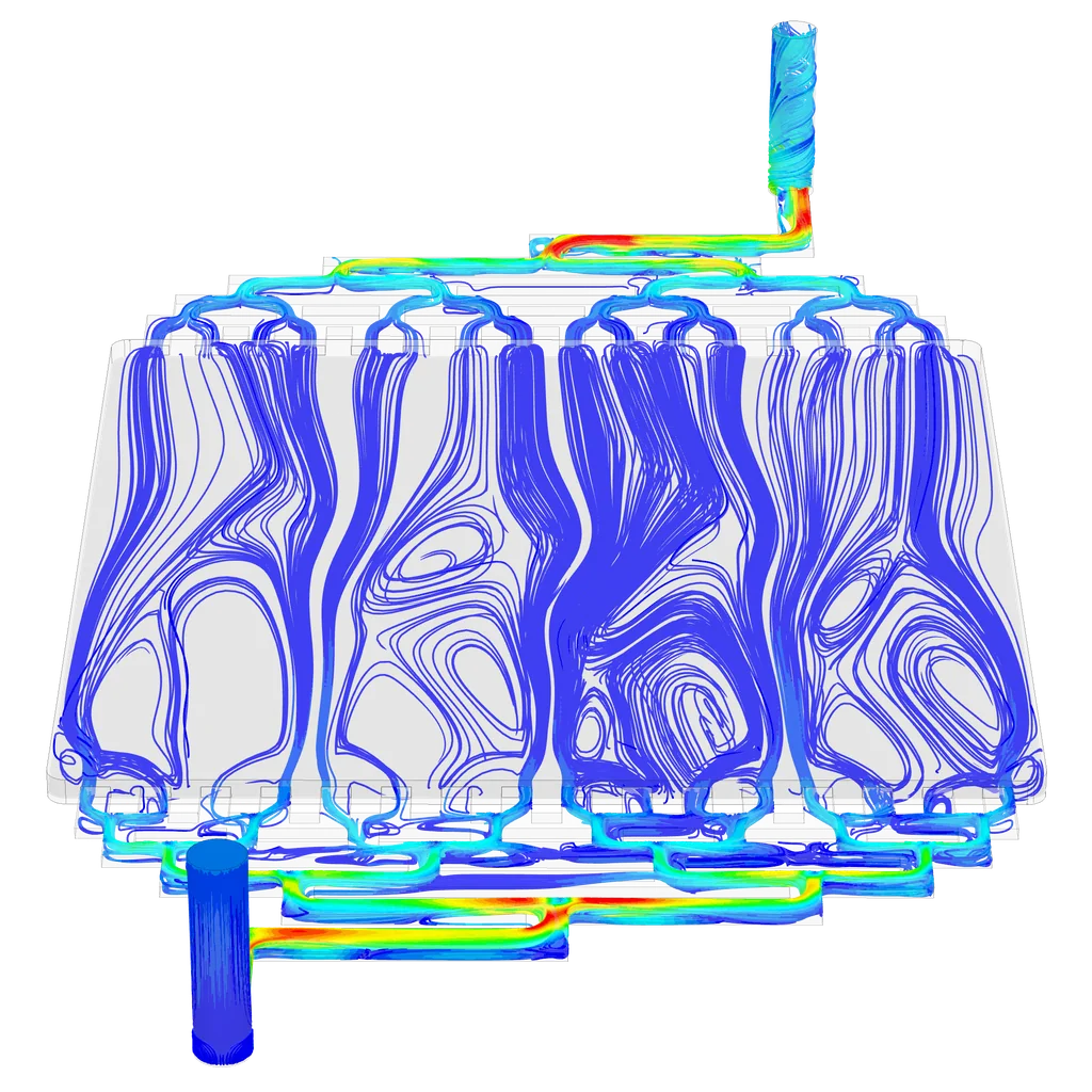
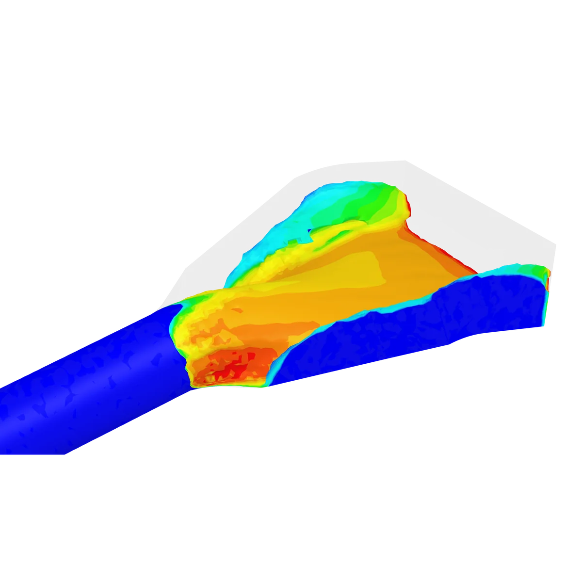
If the expansion rate is wrong and the flow separates from the walls, this can create recirculation zones, increased turbulence, and an uneven velocity distribution, with a high-momentum core or jet persisting through the diffuser. That is precisely the condition to avoid.
“If I increase the velocity and create chaos at the side of the vacuum inlet, the shear stress increases and the pressure differences increase, and that can cause distress or even disease in the fish,” Onur explains.
High wall shear can damage protective mucus, scales, fins and gills, while strong turbulence and unstable flow can increase fish rotation and the probability of wall collisions. Rapid pressure changes are also an important welfare consideration, particularly when they occur over very short timescales. High velocity or disturbed flow at the outlet can also increase the risk of undesirable fish–wall or fish–equipment interactions downstream.
Case Study: From First Concept to Final Geometry
To simulate the vacuum inlet chute, Onur uses multiphase analysis with air and seawater resolved as separate phases, simplifying the model to load the geometry as hard as it will ever be loaded in service. “I simplified it to check the efficiency of the chute on its own,” he says. “This screens the designs using the worst case scenario, with maximum volumetric rate and maximum vacuum.”
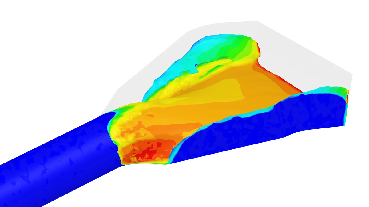
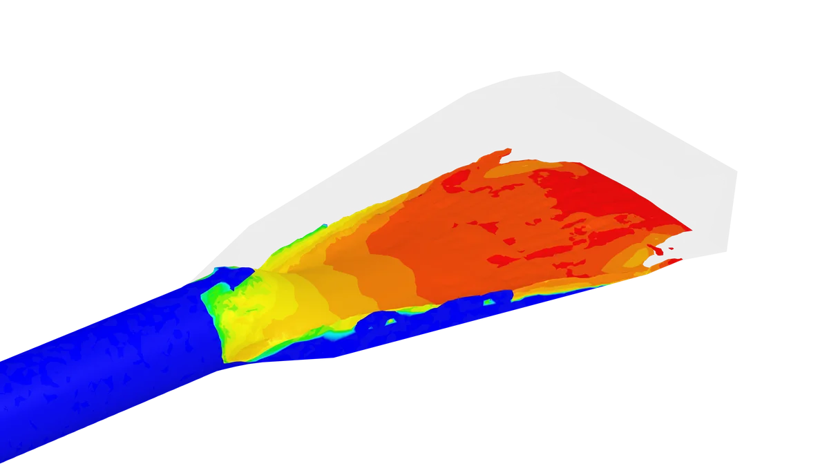
In the example shown above, the first concept tested revealed problematic behavior: separation along the walls, a recirculation zone at the inlet, and an accelerated core. Comparing with the final design (below), we see a component that is sympathetically sized to the onset flow, resulting in much more gradual and even deceleration. “Instead of a sudden expansion, we create a smoother expansion through the outlet,” Onur says. The optimized geometry holds the flow against the walls and brings the peak velocity at the outlet down with it.
Front-loading simulation pays dividends
This example shows the importance of catching problems early. “Instead of redesigning the solid model and the production drawings again and again, we do it one time, and after that we can move forward with confidence,” Onur says. Between the decision time recovered at the front of the project and the downstream work that no longer has to be repeated, he puts the reduction in engineering time on a concept at up to half.
Conclusion: Fish Welfare as an Engineering Specification
Fish welfare in aquaculture is usually discussed as a matter of husbandry or policy. Cflow’s work on the vacuum inlet shows how much of it depends on mechanical engineering of fish transfer systems. Whether a salmon arrives in the hold undamaged comes down to careful design and robust validation before parts are fabricated. Once flow quality is visible, it can be engineered against with the same rigor as any structural requirement.
Concept geometry at Cflow is now validated and refined before the project commits to it, rather than selected on precedent and confirmed later. Cloud-native simulation is what makes that affordable to do, at the same time enabling greater engineering velocity, product quality and operational excellence.
“We have to deliver the fish in the healthiest way to the customer. Our number one aim is to provide a smooth and comfortable journey for the fish, and SimScale gives us the insight we need to do that.”