The real world is unkind to robots. A legged inspection robot has to survive being dropped, knocked, and run through dust and explosive atmospheres. An autonomous vehicle chassis has to withstand many thousands of duty cycles over several years of use. A high-speed actuator has to spin tens of thousands of times a minute without tearing itself apart. And almost every robot has to keep dense electronics cool inside a package that keeps getting smaller. Reliability is not a feature here, it is the product, and the timelines to prove it keep getting shorter.
That pressure is changing how the strongest robotics teams work. Instead of waiting for a prototype to fail on the bench, they are finding the failure in simulation first, while the design is still cheap to change. Cloud-native CFD, FEA, and thermal simulation now let an engineer test a structural variant, a cooling strategy, or a resonance risk in hours, from a browser, without an HPC queue or a dedicated simulation department.
Here are four lessons from robotics and robot-hardware teams who built simulation into the way they design.
Lesson 1: Digitize the Test You Cannot Afford to Run a Hundred Times

The team: ANYbotics, a Swiss company building battery-powered legged robots for autonomous inspection of hazardous industrial sites such as offshore platforms and process plants.
The ANYmal robot has to survive the environments it inspects. Because it operates in potentially explosive atmospheres, it must pass strict compliance testing under IEC 60079, including a structural impact test that fires high-velocity steel balls at the robot to check that nothing deforms enough to ignite the surrounding air or expose the internals. An earlier generation of the robot was failing some of these impact tests, and the physical test gave only a binary answer: pass or fail, with no insight into why.
So ANYbotics rebuilt the test inside SimScale. The team created a virtual version of the steel-ball impact specified in the standard and used FEA to study deformation and residual stress on the protective structures, reading out Cauchy and von Mises stress and displacement directly from the cloud post-processor. Because every run was virtual, they could test as many design variants as they liked, in parallel, without machining a new part for each one.
The insight that came out of it was not “add more material.” When the impact tests showed cracking around a LiDAR protector, intuition said reinforce it with thickness or a tougher alloy, both of which add mass to a weight-critical robot. Instead, the simulations showed that adding a chamfer spread the impact over a larger area, dropping the force per unit area below the damage threshold. The team also ran stair-climbing, rollover, and leg-to-trunk joint fatigue studies, and modelled the electronics cooling, converging on a passive-leaning design with fans running at an efficient 5 watts each rather than large, heavy heatsinks.
“Autonomous robotics require demanding engineering simulation that can account for a broad range of physical phenomena. With SimScale we found our ideal balance between ease of use, variety of capabilities, and the ability to handle complex physics.”— Dr. Alessandro Scafato, Senior Development Engineer, ANYbotics
By moving the test into simulation, ANYbotics reduced the many expensive prototype iterations a robust design used to need down to only a few.
The lesson: When a physical test is slow, costly, or destructive, the highest-value thing simulation does is let you run it a hundred more times. A digitized test turns a pass/fail gate into a design tool.
Read the full ANYbotics case study
Lesson 2: A Small Team Can Explore the Whole Structural Design Space

The team: Ati Motors, a startup developing autonomous cargo vehicles, who needed to design a new chassis without the time or budget for repeated build-and-test cycles.
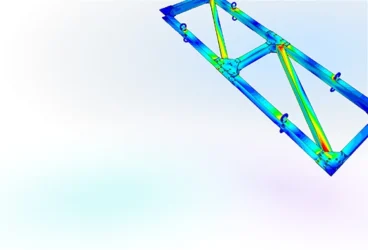
For a young company, every week spent building and manually testing a chassis is a week not spent getting to market. Ati Motors wanted to understand the torsional stiffness of their chassis early, and to iterate on it quickly, but they had no on-premises HPC. The question was whether a small team could run serious structural analysis without that overhead.
They imported their geometry from Onshape into SimScale and set up static structural analyses, applying opposing wheel-reaction loads to measure how the chassis deflected and to extract its torsional stiffness. The models were substantial: a typical run used a mesh of around 2.6 million elements and 9 million nodes, and solved in roughly 15 to 20 minutes on a 64-core cloud cluster. Early on, the team worked through a convergence study with help from SimScale’s support engineers to understand how mesh refinement affected their results, then tuned the mesh down for faster iteration. Across the program they ran more than 80 simulations covering different load cases and design variants.
The payoff was confidence. Stresses and deflections came back within expected ranges for every load case, and the team could explore design changes in the cloud, in parallel, instead of committing to a physical build to find out. The community of public projects and the SimScale forum helped them troubleshoot along the way.
“Being able to run multiple simulations at once, without any hardware constraint, was a welcome feature, and the results give us confidence in the design process.”— Ati Motors
The lesson: Cloud-native FEA removes the infrastructure barrier that used to keep heavy structural iteration out of reach for small teams. Eighty-plus chassis simulations is not a big-company luxury anymore.
Read the full Ati Motors case study
Lesson 3: Find the Resonance Before You Spin Up the Hardware

The team: Carbomech, a startup developing a high-speed air-bearing spindle driven by a DC motor that reaches 180,000 rpm.
At 180,000 rpm, the margins are brutally small. The spindle runs on air bearings with clearances measured in micrometres, which means even a small amount of shaft deformation can drive the shaft into the bearing surfaces and destroy it. Operating anywhere near a natural frequency would deform the shaft exactly that way. Carbomech needed to know, before building, where the safe operating speeds were and how the shaft would deform under load. As a startup, they could not afford to prototype every candidate design to find out.
The team ran modal analysis in SimScale on two spindle designs to identify their natural frequencies and mode shapes, looking for the configuration that balanced stiffness against mass and kept the operating speed safely clear of resonance. They then ran a centrifugal-load analysis at the full 180,000 rpm, using a second-order mesh of around 500,000 elements, to check stress and to calculate how much the critical disk region displaced inside the bearing gap. With that, they defined a speed range the shaft could run in safely.
The commercial result was direct: adding FEA to the design phase let Carbomech build 50% fewer physical prototypes, and with each spindle costing several times a SimScale subscription, the return on investment was high. Their current CM180 spindle was redesigned using the simulation results.
“Adding numerical simulation early in the design phase was the right solution to save time and money, while knowing the results were accurate.”— Carbomech
The lesson: For anything that spins, vibrates, or runs near a natural frequency, modal and harmonic analysis tells you where the danger is before you build the part. Simulation does not just speed up the design; for high-speed hardware it defines the safe operating envelope.
Read the full Carbomech case study
Lesson 4: The Right Solver Lets You Simulate the Real Hardware, Not a Simplified Version

The team: Easee, a Norwegian company whose flagship product, the Easee Charging Robot, is one of the smallest EV chargers on the market.
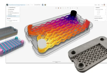
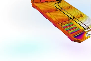
A small, sealed, high-power-density package represents a serious thermal challenge. The Easee Charging Robot packs high charging rates into a tiny enclosure, with internal heat sources and external solar load, and the team deliberately avoided active fan cooling to keep the product small, silent, and reliable. That left passive cooling as the only option, which makes accurate thermal prediction essential. The hard part was the geometry: a real charger model includes the full PCB assembly and even the engravings in the plastic housing, the kind of detail (not needed for simulation) that can consume hours of geometry preparation time in legacy CFD simulation workflows.
Easee used SimScale’s Immersed Boundary Method (IBM) solver to run conjugate heat transfer on the charger. Because the IBM approach immerses the geometry in a cartesian grid rather than meshing every surface, the team could import their complex CAD model as-is, with no simplification, and be solving within about 30 minutes of setup. They also used nonlinear structural FEA to develop the snap-fit features of the molded plastic enclosures, and in one case used a structural simulation to trace a part that was failing unexpectedly back to a supplied-material quality issue.
“The IBM solver made it possible to simulate thermals in our charger, period. This was not possible before IBM or with other CFD tools.”— Andrzej Tunkiel, Mechanical Team Lead, Easee
The cloud side mattered as much as the solver. As Tunkiel put it, “I can run 1, 2, or 20 simulations in parallel without worrying about hardware needs,” which let the team explore and optimize cooling ideas rapidly before committing to a first prototype.
The lesson: Matching the solver to the problem can be the difference between a simulation you can run and one you cannot. For dense electronics packages, the ability to simulate the real geometry without simplifying it away is what makes passive thermal design tractable.
Read the full Easee case study
The Common Thread: Validate Early, Iterate Broadly, Skip the Infrastructure
Four teams, four very different machines: a legged inspection robot, an autonomous cargo vehicle, a 180,000 rpm spindle, and a charging robot. Their engineering problems were structural durability, chassis stiffness, rotordynamics, and electronics thermal. But the way they worked shows the same pattern.
They moved validation upstream. In every case the goal was to answer a hard question before hardware was committed: will it survive the drop test, is the chassis stiff enough, where is the resonance, will the electronics stay cool. Catching those answers early is where the time and cost savings come from.
They iterated in parallel, not in sequence. Eighty-plus chassis runs, two spindle designs compared side by side, twenty cooling simulations at once. None of it required a workstation per engineer or a queue for shared HPC. Cloud compute scaled to the work.
They did it without a dedicated CAE department. Each team pointed to accessibility: browser-based access, fast setup, real support, and CAD that imports cleanly from tools like Onshape. That is what lets a startup or a lean hardware team run analysis that used to need a specialist and a server room.
The robotics market is moving quickly, and the teams shipping reliable hardware are the ones who can test more ideas earlier, without the bottlenecks. Whether the robot walks, drives, spins, or charges, the physics it has to survive is the same physics simulation is built to predict.
Pushing These Workflows Further with Engineering AI and Physics AI
Every story above relied on the FEA, thermal, and CFD solvers at the core of the platform. Two AI systems now sit on top of them and change the economics of this work again. Neither replaces the underlying physics; they remove the slow parts around it.
Engineering AI orchestrates the setup that used to gate every study: importing the CAD assembly, meshing it, applying loads and boundary conditions, and building the parametric sweeps. For the workflows above, that means an impact study, a set of chassis load cases, a modal sweep, or an enclosure thermal model can be stood up in a fraction of the time, and a design engineer can run it without waiting on a dedicated CAE specialist.

Physics AI learns from your high-fidelity results and then predicts new variants in near real time. Instead of running expensive flow and structural solvers on every design candidate, you solve a baseline set, train a model and let Physics AI screen the rest of the design space in seconds. The chamfer that took the impact stress off a sensor protector, the chassis topology that holds the most torsional stiffness, the spindle mass distribution that moves a natural frequency out of the operating range, the vent layout that keeps an enclosure coolest: these many-variant searches are exactly what Physics AI is built to accelerate.
Together they extend every use case in this article in the same direction: broader design-space exploration, earlier in the cycle, with the high-fidelity solver still there to confirm the final candidates before you build.
Validate Your Robot Hardware Before You Build It
SimScale’s AI-native cloud platform brings FEA, thermal, CFD, and electromagnetics simulation into one browser-based environment, with no installation, no VPN, and no HPC to maintain. Whether you are proving a structure against impact and fatigue, sizing cooling for a packed enclosure, or checking a rotating assembly for resonance, you can run it in parallel, from anywhere, from the first day of the design cycle.
Explore SimScale for Robotics Simulation and see how teams like ANYbotics, Ati Motors, Carbomech, and Easee are building tougher hardware, faster.