Electrical and electronic products require specialist design tools throughout the product life cycle to fully optimize their thermal, structural, and design performance. Computational fluid dynamics (CFD) and finite element analysis (FEA) studies are examples of common simulation types used to predict temperatures and stresses and simulate various cooling strategies and components, for example.
Recent advancements have profoundly shifted the legacy product development workflow. Cloud computing has allowed engineers to collaborate in real-time, access advanced simulation capabilities earlier in the design process, obviate costly physical prototyping, and avoid expensive hardware costs. The virtually unlimited computing power and scalability of the cloud mean that deploying these capabilities across an entire distributed engineering organization is now considered a preferred strategy.
Additional benefits of cloud-native simulation include access to 3D parametric scenarios analyses without any impedance to time and computing resources. The value added is the ability to fully explore design space and disqualify poor design candidates earlier in the development process. Application programming interfaces (APIs) further amplify the toolkit available to electronics designers and enable third-party CAD, analysis, optimization, and parametric design tools to talk to each other.
However, common bottlenecks to simulation have been CAD preparation and the numerical discretization of that model (meshing). Both consume time and manual intervention. The advent of advanced physics solvers and novel meshing techniques, such as the immersed boundary method, means that engineers spend less time making their CAD models simulation-ready and more time on insight-driven design. Skipping the time-intensive CAD preparation also opens up the possibility of doing simulations very early when some components are still in the draft stage and comparing many variants that otherwise would have required repeated CAD simplification efforts.
Immersed Boundary Method in SimScale
The Immersed boundary method is based on a cartesian grid, in which the geometry gets immersed. It is resilient to geometrical details and does not require CAD simplification, even for very complex models. Salient features of this approach include:
- Automatic defeaturing of small geometrical details
- Mesh refinements are physics-based rather than geometry-based
- Perfect hexahedral meshes
- Highly flexible mesh sizing from very coarse to very fine for all levels of CAD complexity
The Challenge with Complex CAD Models
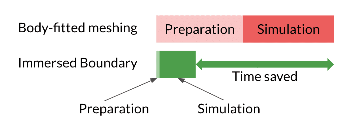
Engineers who want to improve their thermal design by running 3D simulations with conventional tools based on so-called body-fitted meshing are forced to pick the lesser evil of simplifying their CAD model heavily or requiring huge computational resources to simulate.
In any case, they will waste valuable time. Either they spend hours of their limited working time on tedious CAD cleanup and simplification to reduce the model complexity and required computing resources, or they need to put an unreasonable amount thereof to solve the model. While the second approach allows the engineer to continue working on other topics during the calculation, it likely still requires some level of initial CAD cleanup even to get a successful mesh. Additionally, it blocks any advances on their current design for the time the simulation is running, not even speaking about the required hardware costs.
Immersed Boundary Method to the Rescue
The Immersed Boundary method addresses the core of this dilemma. It completely removes the CAD preparation or reduces it to a few minutes at most. At the same time, the physics-driven meshing avoids high mesh resolutions on detailed CAD features that are insignificant to the system’s thermal behavior. Yet, it resolves physically relevant regions like power sources or flow channels to the level the user requires. This level might differ significantly based on the current simulation intent.
Early in the design process, the engineer might be more interested in qualitative insights into the thermal management concepts he is experimenting with. Those simulations often only require coarse mesh resolutions. Body-fitted approaches do not allow this design space as the geometric details always lead to large mesh sizes (see Figure 2 above).
Later in the process, the focus shifts towards quantitative results, such as maximum temperatures on critical components. In order to provide the required accuracy, the mesh resolution required by body-fitted and IBM meshing will be closer. The CAD preparation time, of course, remains as saved time, and the engineer benefits from the underlying solving based on the same high-fidelity finite volume implementation in both cases.
The Main Benefits for Engineers
Summarizing the main benefits for the engineer, immersed boundary method enables you to:
- Simulate early in the design phase when parts of the system are in the concept phase
- Simulate the detailed original model without the need for CAD preparation
- Run extensive design of experiment studies
- Derive accurate critical temperatures during the validation phase
The graphic below shows how an important result quantity e.g. the junction temperature of a chip changes with higher mesh resolutions i.e. higher computational costs for body-fitted and IBM-based simulations.
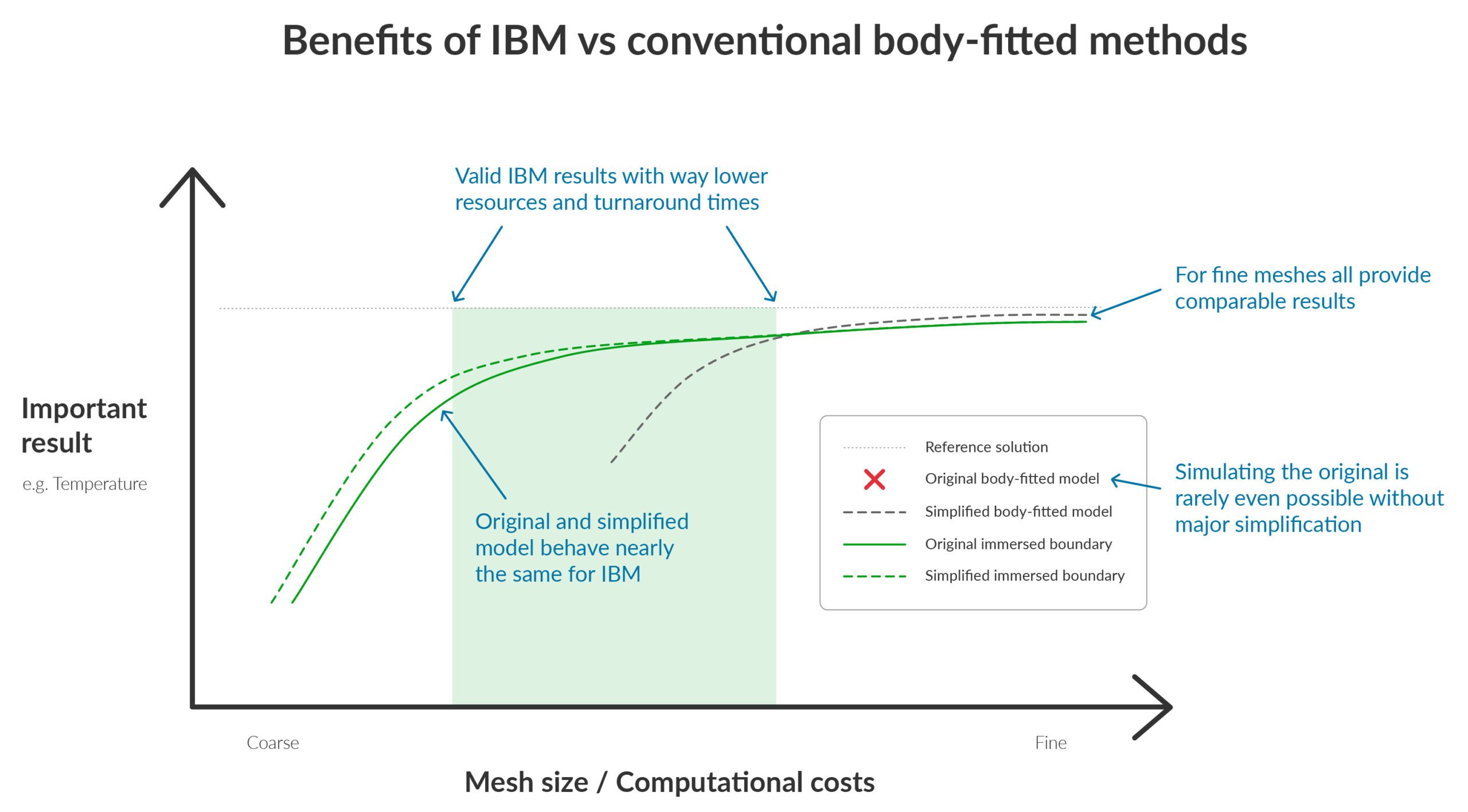
So what’s the catch? Well, there is no catch. The Immersed boundary method is a perfect fit for thermal engineers dealing by default with complex systems and looking for optimization insights throughout the design process.
Suppose an engineer is looking for a very accurate representation of the flow boundary layer, for example, when designing fan blades or something similar. In that case, it usually makes more sense to capture the physical effect with mesh boundary layers and prepare the CAD for a conventional body-fitted simulation.
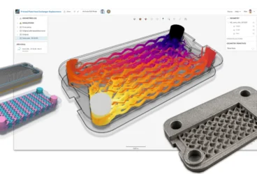
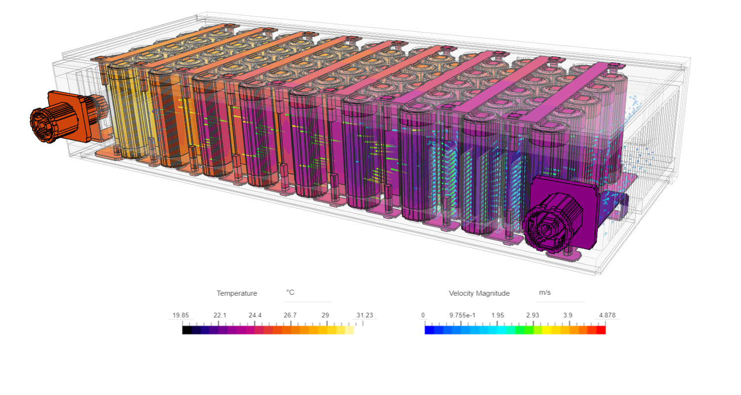
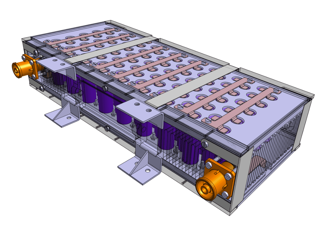
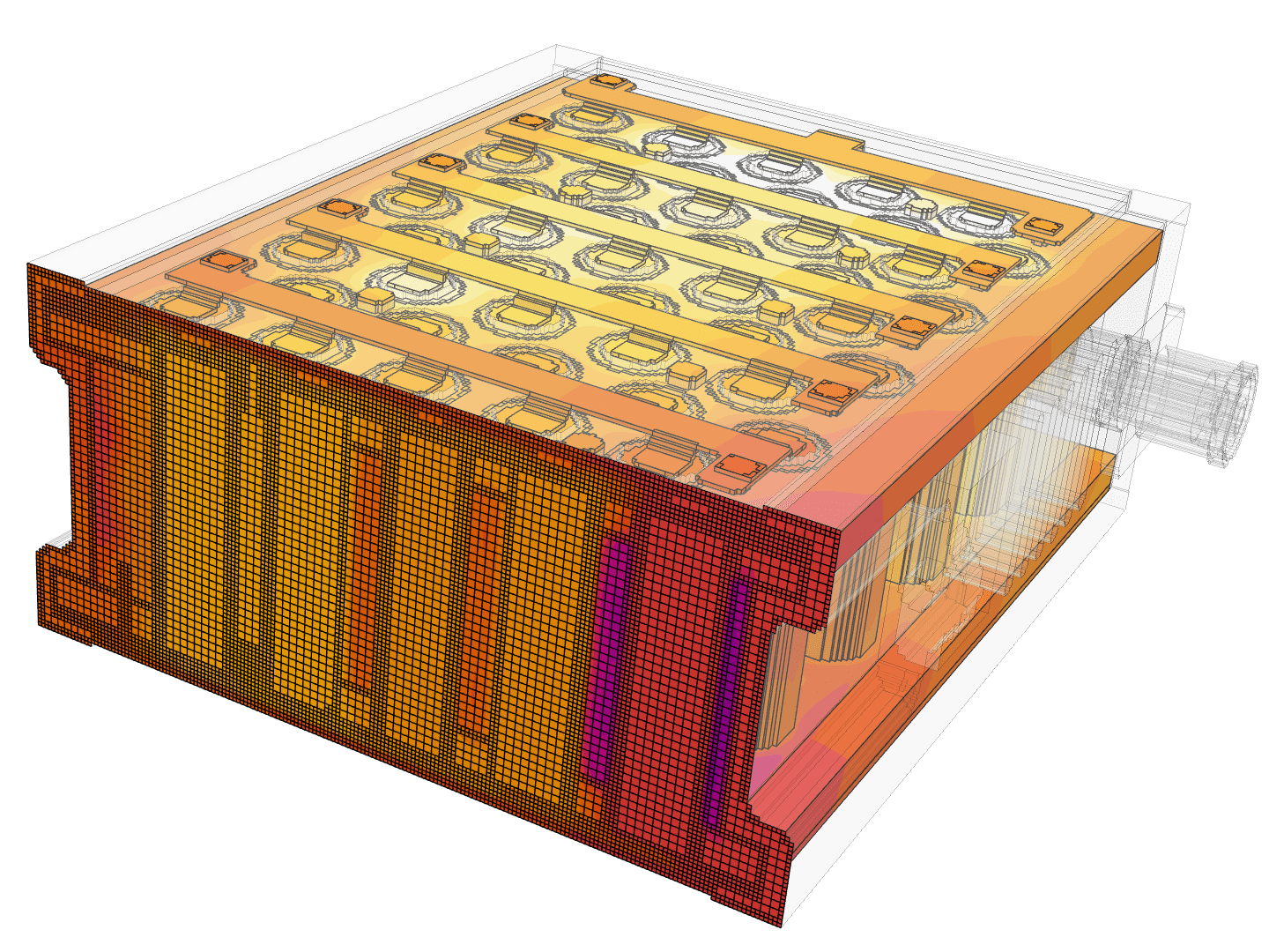
A Case Study of an Electric Vehicle Battery Pack
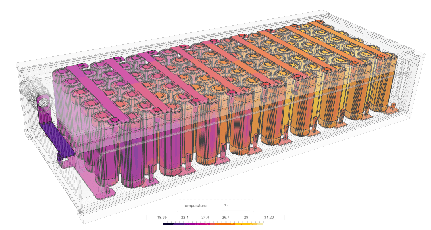
We have shown a case of an electric vehicle battery pack. The design is an example of an air-cooled lithium-ion battery model for an FSAE electric race car, which is utilized as the accumulator to power the car. Effective thermal management of the battery pack is essential to ensure the reliable and safe operation of the battery cells and hence the car.
When the rest of the vehicle design is constantly changing to meet performance objectives, a continuous update in the battery pack is also required to align with these evolving design parameters. Throughout each design iteration, key questions arise regarding the amount of heat generated within the batteries for relevant duty cycles and the necessary air flow rate to maintain the battery pack within its designated temperature range.
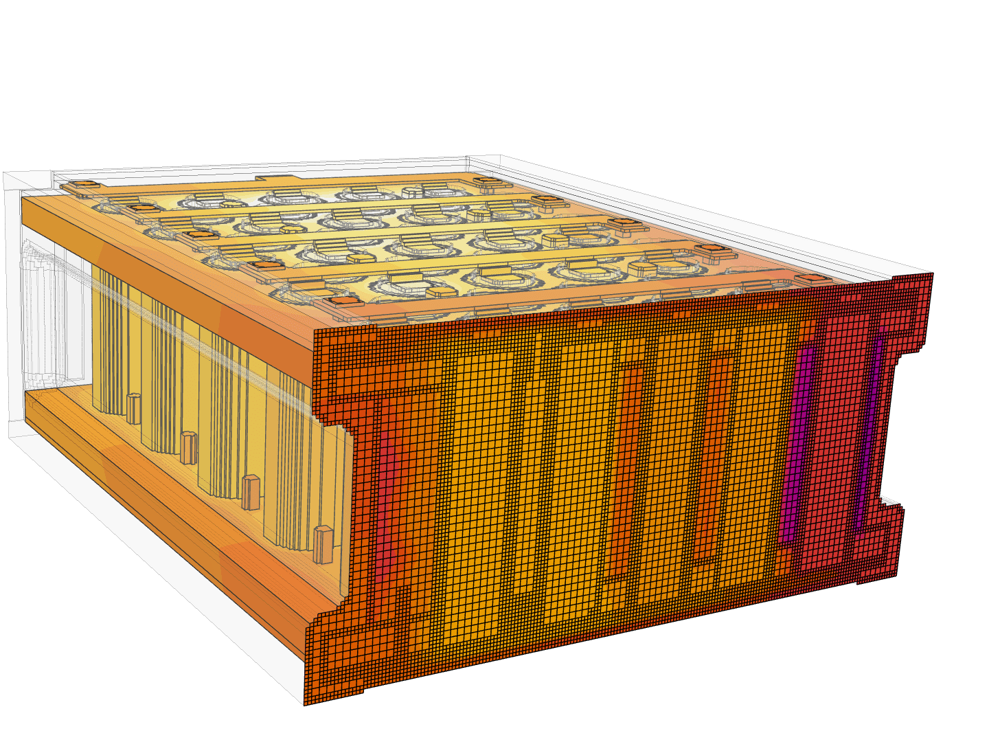
Finding accurate answers to these questions using a robust electronics cooling simulation not only increases the confidence in the design but also makes it possible to get those answers faster, even when the model is geometrically very detailed. The provided example demonstrates the significant advantage of the immersed boundary method in handling geometrical details without the need for CAD simplification. As a result, valuable insights can be swiftly obtained from each design iteration, enabling a more efficient and thorough evaluation of the design without compromising accuracy or intricate geometric details.
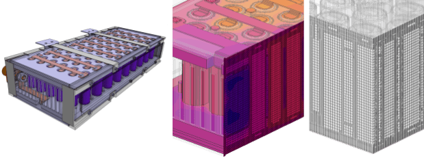
Comparing Meshing Methods
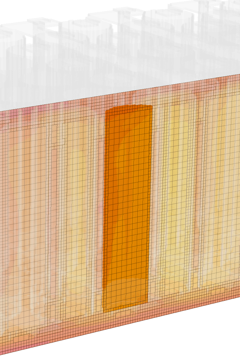
In this battery pack example, we attempted to simulate both the original and simplified versions of the CAD model using Conjugate Heat Transfer analyses with body-fitted and Immersed Boundary Method solvers. The main advantage of using the cartesian mesh-based Immersed Boundary Method is that it allows us to overcome the inability to mesh the original model using a body-fitted mesh. By immersing the geometry into the cartesian grid, the cartesian mesh automatically defeatures small geometrical details.
Whereas to prepare the model for CHT analysis, we need to invest time in CAD cleaning. This involves removing small details that do not directly impact the problem’s physics and achieving an efficient mesh size without unnecessary refinements. The time devoted to cleaning the small geometric details for the body-fitted mesh, in this case, ~ 2.5 hours, can be instead well-spent on design iterations when using the immersed boundary method.
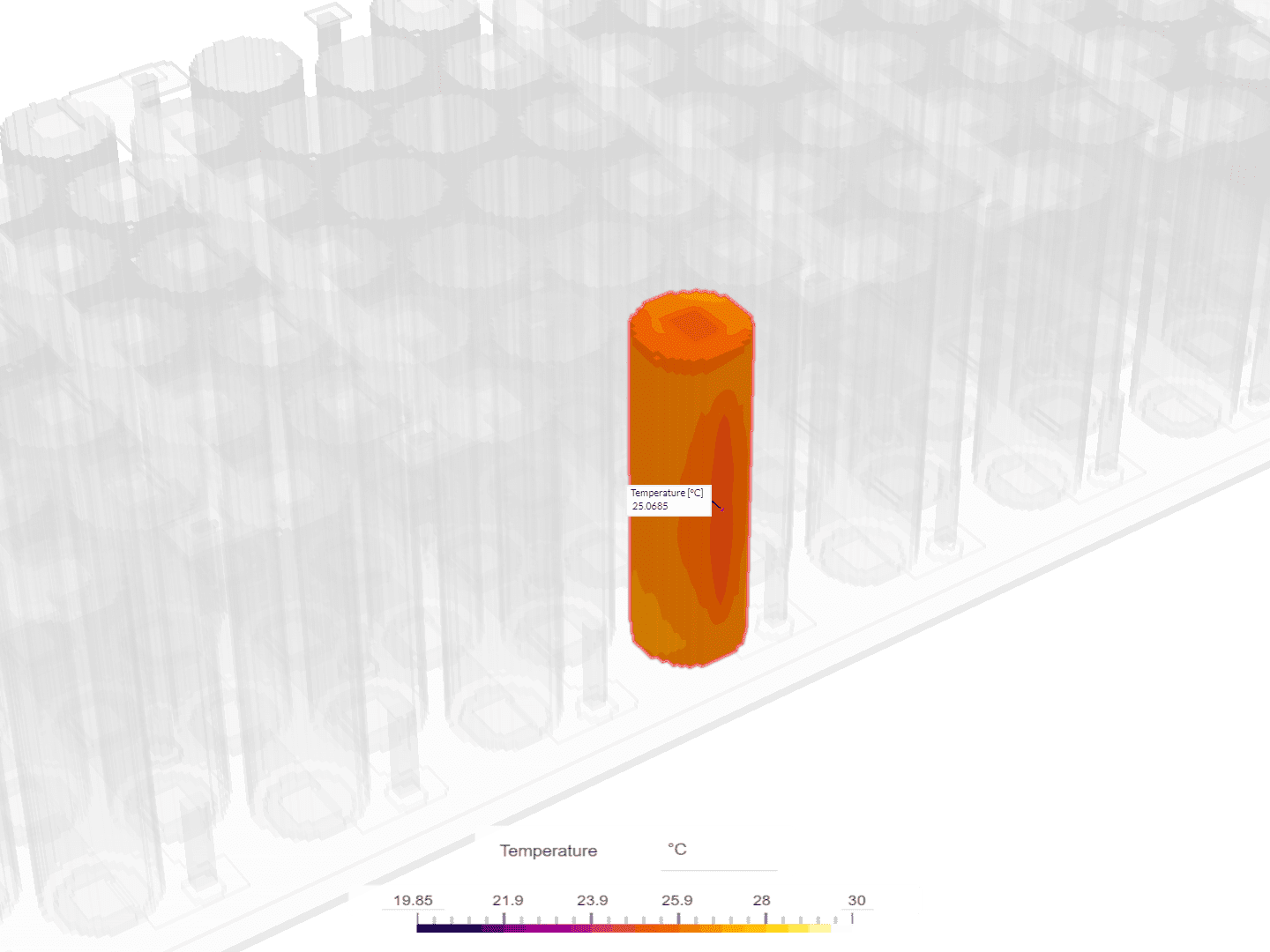
| Mesh | Number of cells | Run time [minutes] | Resources [core hours] | Temperature of a single battery [°C] |
|---|---|---|---|---|
| Standard body-fitted mesh of the CAD (simplified) model | 9.7 million | 253 | 404.80 | 23.86 |
| Cartesian mesh of the original model – immersed boundary | 2.9 million | 141 | 225.60 | 24.05 |
| Cartesian mesh of the simplified model – immersed boundary | 2.7 million | 97 | 156.80 | 23.86 |
Benefits of Using the Immersed Boundary Analysis in SimScale
Based on the results of the two different methods, the benefits of using IBM can be summarized as follows:
- Automatic handling of small details: With IBM, the geometry is ready for simulation without the need for CAD cleaning, even when the original model contains numerous small details. In contrast, CHT relies on a body-fitted mesh, and if the unsimplified original model is not simulation-ready, additional effort must be spent on CAD cleaning.
- Computational efficiency: By manually cleaning the small details in the geometry, the model becomes ready for CHT. Even when this is the case, IBM requires significantly fewer computational resources than CHT. With IBM, the mesh size is reduced by 72%, computational resources are reduced by 61%, and the runtime is reduced by 62%. Moreover, the results of the two analysis methods are almost identical (0.002% difference), demonstrating the accuracy of using IBM for design iterations while efficiently utilizing resources.
- Effective design exploration: Even when the original model is simulated using IBM, the computational resources required are still much less compared to the simplified model simulated with CHT. The mesh size of the original model with IBM is reduced by 70% compared to the simplified model with CHT, while both the computational resources and the runtime are reduced by 44%. This highlights that without wasting time cleaning the model, multiple design iterations can be tested without the overhead of fine mesh regions around insignificant details. Consequently, the time required for users to discover the best design is significantly shortened.