
A building can hit every energy target in its spec and still generate complaints from the day it opens. Occupants sit in a draft from a badly placed diffuser, or in the cold spot under a curtain wall, and the whole-building average that looked fine on paper never described the seat they are in. ASHRAE 55 is the standard that turns “too cold” into a number you can design against, and it is the reason thermal comfort gets checked before the ductwork is ordered rather than after the first summer.
This article covers what the standard specifies, the six factors it works from, the comfort zone and how to read it, the two calculation methods and when each applies, what compliance documentation has to contain, and how CFD simulation resolves comfort across a space instead of at a single point.
What is ASHRAE 55?
ANSI/ASHRAE Standard 55, “Thermal Environmental Conditions for Human Occupancy”, specifies the combinations of indoor environmental factors and personal factors that produce conditions acceptable to a majority of occupants in a space. It is published by the American Society of Heating, Refrigerating and Air-Conditioning Engineers, and the current edition is 55-2023, which supersedes 55-2020.
ASHRAE 55 defines thermal comfort as “that condition of mind that expresses satisfaction with the thermal environment”, and is used primarily in the United States but is well known around the world as the standard for designing, commissioning, and testing indoor spaces and systems written in parallel with other well known international standards such as ISO 7730.
The standard applies to healthy adults, in spaces occupied for 15 minutes or longer, at altitudes up to 3,000 m (10,000 ft). It sets criteria for whole-body comfort and for local discomfort, and it defines what a design team has to document to show it met them.
Run a thermal comfort simulation in your browser
Set up PMV and PPD result fields on your own geometry and see where the criteria are met.
The six factors of thermal comfort
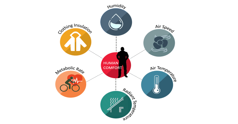
Thermal comfort depends on six factors, and ASHRAE 55 requires all six to be accounted for in combination. Four are environmental and two are personal.
Environmental:
- Air temperature. The dry-bulb temperature of the air around the occupant.
- Mean radiant temperature. The area-weighted average temperature of the surrounding surfaces, which is why a seat next to a cold window feels colder than the thermostat reading.
- Air speed. The rate of air movement at the occupant, regardless of direction.
- Humidity. Usually expressed as relative humidity or humidity ratio.
Personal:
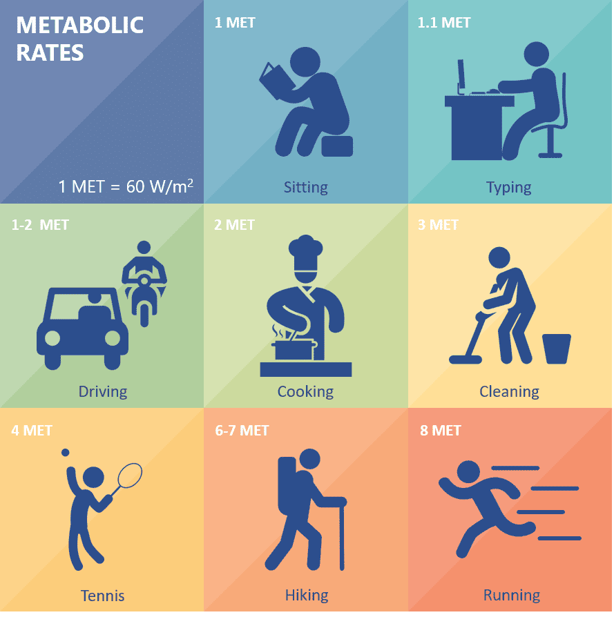
- Metabolic rate, in met. 1 met is a person at rest; office work is roughly 1.1 to 1.2 met.
- Clothing insulation, in clo. 1 clo is a typical winter ensemble, 0.5 clo a summer one.
Change any one of the six and the acceptable range for the others moves with it. That is why ASHRAE 55 never publishes a single “comfortable temperature”: the answer depends on the other five.
Thermal comfort: the history of ASHRAE 55
ASHRAE 55 is currently in its 2023 edition. The standard was first published in 1966 and is updated every 3-7 years based on current research, practical experience, and recommendations from designers, manufacturers, and end users, under a continuous maintenance process that folds in addenda between full editions.
ASHRAE Standard 55 – 2004
The 2004 ASHRAE update introduced a few critical changes that lessened the criteria gap between it and its ISO standard counterparts. This included the adoption of the computer model method, the introduction of the adaptive method (or model that relates indoor design temperature ranges to outdoor meteorological parameters) based on research that supports natural ventilation designs, and the recognition of elevated airspeed preference for general occupant thermal comfort.
ASHRAE Standard 55 – 2010
The 2010 update reintroduced standard effective temperature (SET) as the method of evaluating and determining the cooling effect of elevated airspeeds and indoor air movement as a whole, made large revisions to clearly specify mandatory minimum requirements in both design analysis and documentation to comply with the standard, and added a general satisfaction survey and post-occupancy evaluation (POE) as a method of preemptively as well as retroactively evaluating thermal comfort for occupants in a space.
ASHRAE Standard 55 – 2017
The 2017 ASHRAE 55 standard update includes a new element that can take into consideration the change in occupants’ thermal comfort from direct solar radiation, in addition to the existing scope, requirements, conditions, and parameters.
ASHRAE Standard 55 – 2020
The 2020 edition rolled in eight addenda. It added an ankle draft risk assessment method, introduced Thermal Environmental Control Classification Levels to structure the required documentation, replaced the old Graphic Method with analytical and elevated air speed methods, and extended the adaptive model to mechanically cooled buildings during periods when the cooling system is not operating.
ASHRAE Standard 55 – 2023
The current edition incorporates eleven addenda to 55-2020. The main changes:
- A new method for assessing local thermal discomfort caused by vertical air temperature gradients.
- Metabolic rate applicability extended to 4 met, up from 2 met, which brings light industrial and active occupancies into scope.
- The calculation methods consolidated down to two, the standard method and the adaptive method, with a flowchart for selecting between them.
- Section 6 documentation requirements rewritten, with a compliance spreadsheet form.
If a project specification, code, or rating system names a specific edition, that edition governs. LEED v4, for example, still cites 55-2010. Absent a named edition, design to 55-2023.
The scope of ASHRAE 55
The standard was designed primarily for spaces where occupants are sedentary, office work being the reference case, but it covers other indoor environments too. Extreme conditions fall outside it and sit with ISO 7243, ISO 7933, and ISO/TR 11079. Two limits are worth noting: ASHRAE 55 says nothing about air quality, acoustics, illumination, or contamination, which EN 16798-1 covers alongside comfort, and it treats only steady-state cases. For comfort over a period of time, see ISO 7730 Section 9.
Important ASHRAE 55 terminology for understanding thermal comfort
Environmental factors and inputs
Airspeed
The rate of air movement at a given point in time regardless of the direction.
Clo
The unit of thermal insulation from clothing, where 1 clo is a winter ensemble and 0.5 clo a summer one. Clothing insulation (Icl) includes the parts of the body left uncovered; garment insulation (Iclu) covers only heat transfer through skin-to-clothing contact.
Metabolic rate (M)
The rate at which the body converts chemical energy into heat and mechanical work, expressed per unit area of total body surface. ASHRAE 55 states it in met units, where 1 met is a person at rest.
Relative humidity (RH)
The ratio of the partial pressure of water vapor in the air to the saturation pressure of water vapor at the same temperature and total pressure.
Mean radiant temperature (tr)
The uniform surface temperature of an enclosure in which an occupant would exchange the same amount of heat as in the actual non-uniform space. It is the area-weighted average of the surrounding surface temperatures.
Predictive results and outputs
Predicted mean vote (PMV)
An index that predicts the mean value of votes of a group of occupants on a seven-point thermal sensation scale, based on the balance of heat within the human body. That balance is reached when an occupant’s internal heat production equals their heat loss. PMV is computed for a given combination of metabolic rate, clothing insulation, temperature, airspeed, mean radiant temperature, and relative humidity.
| PMV value | Thermal sensation |
|---|---|
| +3 | Hot |
| +2 | Warm |
| +1 | Slightly warm |
| 0 | Neutral |
| -1 | Slightly cool |
| -2 | Cool |
| -3 | Cold |
Predicted percentage of dissatisfied (PPD)
An index that predicts the percentage of thermally dissatisfied occupants, too warm or too cold. PPD is calculated from the PMV. It never falls below 5%, because a fraction of any population is dissatisfied even at perfect neutrality.
Standard effective temperature (SET)
The temperature of an imaginary standard environment, at 50% relative humidity and still air, in which a person in standard clothing would lose heat at the same rate as in the actual environment. SET is what lets the standard quantify the cooling benefit of elevated air speed.
Additional thermal comfort terminology to note
Thermal neutrality
The indoor thermal index value corresponding with a PMV vote of neutral on the thermal sensation scale.
Local discomfort
Unwanted cooling or heating on a particular part of an occupant’s body. Main causes are draft, high vertical temperature differences between head and ankles, floors that are too warm or too cold, and radiant temperature asymmetry. A wall at 343 K facing one at 273 K produces a gradient the occupant feels as discomfort even when neither temperature is intolerable.
The ASHRAE 55 comfort zone and how to read the comfort chart
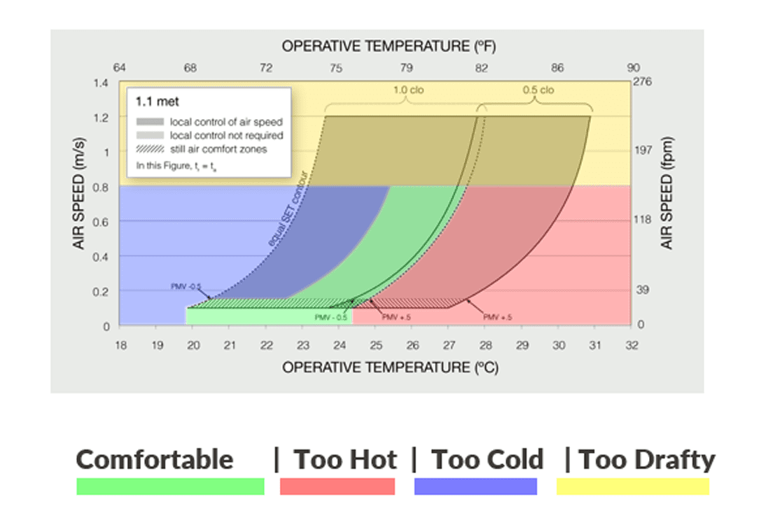
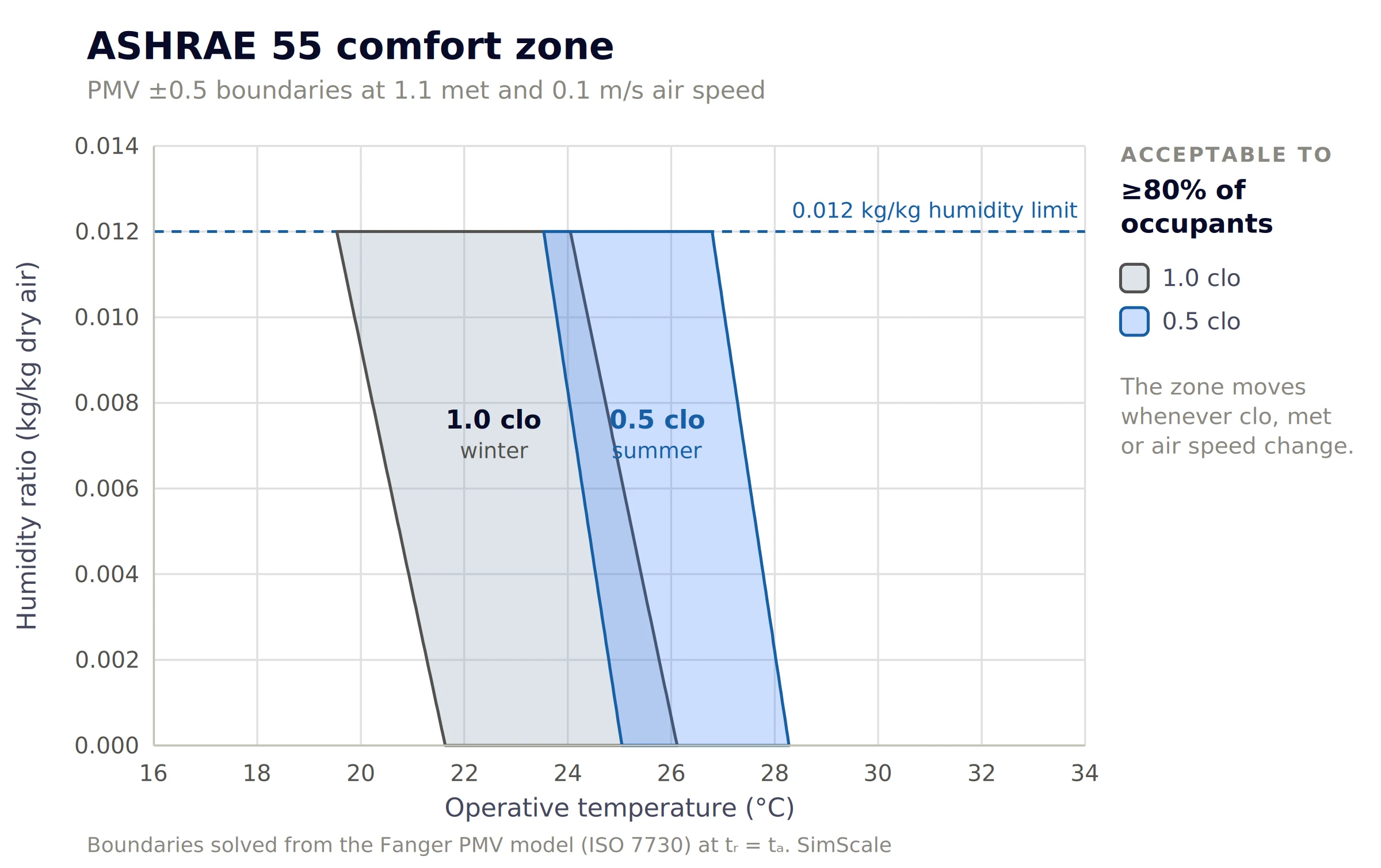
The ASHRAE 55 comfort zone is the range of operative temperature and humidity combinations that at least 80% of occupants find acceptable, at a stated air speed, metabolic rate, and clothing level. It is drawn as a polygon on a psychrometric chart, with operative temperature on the horizontal axis and humidity ratio on the vertical.
Reading it takes three steps:
- Fix the assumptions. The zone is only valid for the clo and met values it was drawn for. A zone plotted at 0.5 clo and 1.1 met describes a summer office, not a workshop.
- Plot the design point. Use operative temperature, which combines air temperature and mean radiant temperature, not the thermostat setpoint.
- Read the direction of any miss. A point sitting to the right of the polygon is too warm, above it is too humid. The axis you exceeded tells you which system parameter to change.
Two zones are usually shown on the same chart, one for winter clothing (around 1.0 clo) and one for summer clothing (around 0.5 clo). They overlap in the middle, and the gap between their outer edges is the reason a single year-round setpoint tends to disappoint someone in every season.
Two limits bound the chart itself. Humidity ratio has an upper limit of 0.012 kg water per kg dry air (roughly 60 to 65% RH at typical room conditions). ASHRAE 55 sets no lower humidity limit for thermal comfort, though designers commonly target 30 to 60% RH for other reasons.
ASHRAE 55 comfort criteria at a glance
The standard’s numeric criteria fall into three groups: whole-body comfort, local discomfort, and temperature variation over time.
| Criterion | Limit |
|---|---|
| PMV for compliance | -0.5 to +0.5 |
| PPD for compliance | 10% or below |
| Humidity ratio, upper limit | 0.012 kg/kg dry air |
| Humidity, lower limit | None specified for thermal comfort |
| Air speed for draft control below 22.5 °C (72.5 °F) | 0.15 m/s (30 fpm) or below |
| Air speed above which elevated-air-speed methods apply | 0.20 m/s (39 fpm) |
| Elevated air speed, naturally conditioned spaces | up to 1.2 m/s (240 fpm) |
| Vertical air temperature difference, head to ankles | 3 °C (5.4 °F) seated, 4 °C (7.2 °F) standing |
| Floor surface temperature | 19 to 29 °C (66 to 84 °F) |
| Temperature drift, uncontrolled conditions | 1.1 °C (2.0 °F) per 15 min, 2.2 °C (4.0 °F) per hour |
| Metabolic rate range in scope (55-2023) | 1.0 to 4.0 met |
| Occupancy duration in scope | 15 minutes or longer |
| Altitude in scope | up to 3,000 m (10,000 ft) |
There is no single ASHRAE 55 temperature range. The figures often quoted, roughly 20 to 23.5 °C (68 to 74 °F) in winter at 1.0 clo and 23 to 26 °C (73 to 79 °F) in summer at 0.5 clo, are comfort zone outputs computed at those specific assumptions, not text lifted from the standard. Quote them as typical office results, and compute the zone for the actual clo and met of the space being designed.
Values here are summarized from published documentation of the standard. Verify against the licensed text of ANSI/ASHRAE 55-2023 before using them in a compliance submission.
The two ASHRAE 55 methods: standard (PMV) and adaptive
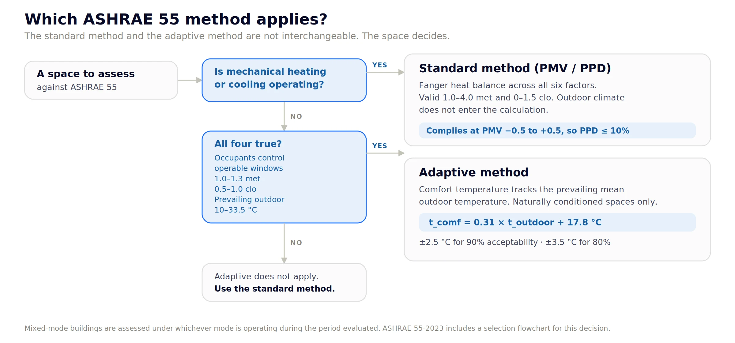
ASHRAE 55-2023 offers two calculation methods, and picking the wrong one is the most common way a comfort analysis goes wrong. The standard method applies to mechanically conditioned spaces. The adaptive method applies only to naturally conditioned spaces.
The standard method
The standard method uses Fanger’s PMV/PPD heat balance model: all six factors in, a predicted mean vote out, converted to a predicted percentage of dissatisfied. Compliance means PMV between -0.5 and +0.5, so PPD at or below 10%. It applies where mechanical heating or cooling is operating, for 1.0 to 4.0 met and 0 to 1.5 clo. Outdoor climate does not enter the calculation.
The adaptive method
The adaptive method ties the acceptable indoor operative temperature to the prevailing mean outdoor temperature, on the evidence that occupants in naturally ventilated buildings adjust their clothing, their expectations, and their windows. The comfort temperature follows:
t(comfort) = 0.31 × t(outdoor, prevailing mean) + 17.8 °C
in Fahrenheit, t(comfort) = 0.31 × t(outdoor) + 54.1 °F
Acceptability bands sit around that line: ±2.5 °C for 90% acceptability and ±3.5 °C for 80%.
It is valid only when occupants control operable windows, no cooling or heating is running, metabolic rates are 1.0 to 1.3 met, clothing is 0.5 to 1.0 clo, and the prevailing mean outdoor temperature is between 10 and 33.5 °C (50.0 and 92.3 °F). Since 55-2020, a mechanically cooled building can be assessed this way during periods when the cooling is off.
A mixed-mode building is assessed under whichever mode is operating during the period being evaluated. ASHRAE 55-2023 includes a selection flowchart for exactly this decision.
Elevated air speed and the cooling effect
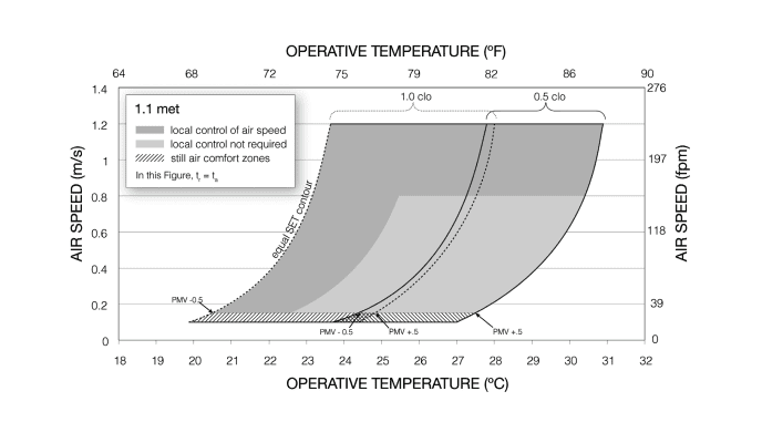
Air movement above 0.20 m/s raises the upper temperature limit of the comfort zone, which is how a design can stay comfortable at a higher setpoint and use less cooling energy. ASHRAE 55 quantifies the trade using SET: the elevated air speed is credited with the temperature offset that produces the same SET.
The credit comes with caps. Above 22.5 °C, air speed can go to 0.8 m/s without local occupant control, and to 1.2 m/s where occupants can control it themselves. Below 22.5 °C the concern reverses and air speed has to stay at or below 0.15 m/s to avoid draft.
Air speed is also the factor that varies most across a room. A ceiling fan or a supply diffuser produces a field, not a value, and the difference between 0.2 m/s and 0.8 m/s can be one row of desks. Point calculators cannot resolve that; CFD can.
General requirements and standard conditions of ASHRAE 55
Sections 4 and 5 of ASHRAE 55 define the requirements and conditions for compliance. The standard has to be applied to the particular space, its occupants, the locations within it if not the whole space, and any outlier occupants such as children, elderly or disabled people.
The mandatory conditions are ranges rather than single values, because physiological and psychological variation makes satisfying everyone impossible. ASHRAE 55 therefore sets a percentage of occupants that constitutes acceptability, and the thermal conditions associated with that percentage.
Compliance with ASHRAE Standard 55
A space complies when at least 80% of occupants can be expected not to object to the conditions, which means the majority sit between -0.5 and +0.5 on the PMV scale. Building systems, natural or mechanical ventilation, controls and thermal envelopes alike, must hold conditions within that range using one of the methods in section 5, account for all expected conditions (summer and winter, excluding extremes), and carry the documentation below.
Needed thermal comfort compliance documentation
The documentation needed to comply with ASHRAE must consist of all of the following, except in the case of naturally ventilated spaces:
- The design operative temperature, humidity, and total indoor loads.
- The hours of each seasonal exceedance associated with the outdoor weather percent design conditions.
- The values assumed for comfort parameters (clothing insulation, metabolic rate, indoor airspeed, etc.) at the different assumed conditions (i.e., seasonal).
- Local discomfort effects (i.e., if someone sits next to a radiator or right below a cooling vent this can lead to local discomfort although the entire space overall is in thermal equilibrium. These effects can easily be determined using thermal modeling tools like SimScale).
- The system input or output capacity needed to attain the design operative thermal conditions.
Since 55-2020, the documentation is organized by Thermal Environmental Control Classification Level, and 55-2023 supplies a compliance spreadsheet form for it.
A final conclusion can not be made about naturally conditioned spaces vs. spaces with other types of mechanical ventilation systems. Occupants’ expectations simply are not the same everywhere, and having simple variables such as the ability to open a window usually comes with a higher acceptance of volatility of temperature and draft.
Evaluating comfort in an existing building
For a building already in use, ASHRAE 55 provides a survey route alongside physical measurement. Occupants vote on the seven-point thermal sensation scale, and the space passes when at least 80% are satisfied.
Response rate requirements scale with occupancy: at least 35% for populations above 45 occupants, at least 15 responses for populations of 20 to 45, and an 80% response rate for fewer than 20. Where physical measurement is used instead, air temperature, mean radiant temperature and humidity are logged at intervals of no more than 5 minutes and air speed at no more than 3 minutes. Building automation data can substitute at intervals of no more than 15 minutes spanning at least 30 days.
Is ASHRAE 55 mandatory?
ASHRAE 55 is a voluntary consensus standard, not a building code. It becomes binding only where something else references it: a project specification, a green building code such as ASHRAE 189.1 or the IgCC, or a rating system.
- LEED. The BD+C Thermal Comfort credit requires design to ASHRAE 55-2010 plus individual comfort controls for at least 50% of occupant spaces. A companion occupant survey credit triggers corrective action when more than 20% of respondents are dissatisfied.
- WELL. The T01 Thermal Performance precondition requires ASHRAE 55, or an equivalent such as EN 16798-1 or ISO 7730, verified by documentation and on-site performance testing.
Energy codes are a separate matter. ASHRAE 90.1, the IECC and Title 24 regulate energy use, not comfort, and a design can satisfy all of them and still fail ASHRAE 55.
ASHRAE 55 vs ISO 7730 and EN 16798-1
All three use the same six factors and the same Fanger heat balance model. They differ in how they band the results and in what else they cover.
| ASHRAE 55 | ISO 7730 | EN 16798-1 | |
|---|---|---|---|
| Primary market | United States | International | Europe |
| Comfort categories | Single PMV/PPD criterion | Three categories (A, B, C) | Four categories (I to IV) |
| Adaptive model | Yes | No | Yes, different regression and bounds |
| Elevated air speed / SET | Yes | No | Limited |
| Occupant survey route | Yes | No | Yes |
| Scope beyond thermal | No | No | Also IAQ, lighting, acoustics |
The adaptive models in ASHRAE 55 and EN 16798-1 are not interchangeable: the regressions and validity bounds differ, so a design that passes under one does not automatically pass under the other. For the full side-by-side, see ASHRAE 55 and ISO 7730 and what EN 16798 covers.
How SimScale calculates thermal comfort and evaluates local discomfort
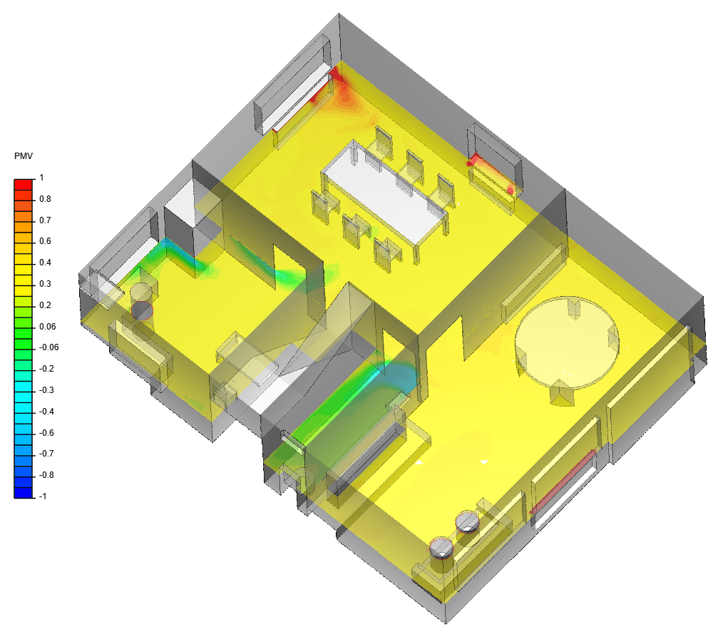
SimScale’s cloud-native simulation platform computes PMV and PPD as fields using the Fanger model, following the static model for thermal comfort. The inputs are temperature and air speed (the standard recommends an adaptation above 0.2 m/s), together with clothing insulation, relative humidity, and mean radiant temperature. See the Thermal Comfort Parameters documentation for the setup.
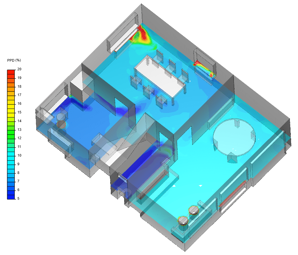
Because the solver returns a field rather than a single value, the results resolve where in the room the criteria are met and where they are not. That distinction matters for the local discomfort limits, since a vertical gradient of 3 °C head to ankles or a floor outside 19 to 29 °C is a property of a location, not of a space average. Mean radiant temperature comes out of the same solve when radiation is included, which is what makes the cold spot next to a glazed facade visible before it is built. See the SimWiki entry on mean radiant temperature and operative temperature for the underlying definitions.
How CFD simulation can help you comply with ASHRAE Standard 55
Until recently, HVAC design engineers mainly relied on hand calculations in their efforts to comply with ASHRAE 55 and other standards. Today, with the advent of accessible and easy-to-use computational fluid dynamics (CFD) simulation tools, designers can virtually test and refine their HVAC systems in the earliest stages of the design process, intercepting design flaws without building physical prototypes.
Point calculators such as the CBE Thermal Comfort Tool and the ASHRAE Thermal Comfort Tool answer the question for one set of conditions, which is the right check for whether a given combination of the six factors lands inside the comfort zone. CFD answers a different question: where in this room the conditions actually occur, and which seats fall outside the criteria.
Fusion Modulair used SimScale to evaluate a modular ventilation system for a 55,000 m² warehouse in Australia. In the summer design case, at 37 °C ambient and 32.2% RH at peak, “Fusion’s system maintains good thermal comfort internally showing an average PMV of -0.1, an average PPD of 10%, and an internal average temperature of 25.5°C.” Ken Thomson, Senior Engineer, Energy, HVAC and ESD Services at Fusion Modulair, on the scale of it: “The technical capabilities and serious grunt of the SimScale software solution allowed Fusion Modulair to complete over 22,000 core hours of computational processing time, in a 3-week window.” Read the Fusion Modulair case study.
To see a live demonstration of how CFD simulation can help you ensure thermal comfort in indoor spaces and comply with the ASHRAE Standard 55, watch this webinar:
Case study: ensuring thermal comfort in a theater room through ventilation
The project used for this case study is available as a step-by-step walkthrough: Advanced tutorial: thermal comfort in a theater room, which analyzes duct positioning inside the same theater room and links to the finished simulation in the workbench.
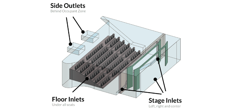
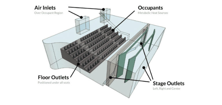
The study designs an HVAC system for a large theater room, with inlet and outlet ventilation locations as the design variables. SimScale’s convective heat simulation analyzes an initial configuration, a second configuration addresses the flow issues it reveals, and a follow-up analysis quantifies the improvement.
In the first design the inlets sit on top with no diffusers. In the second, the inlets move underneath the seats and to the stage floor, where the previous outlets were, and two large outlets go behind the last row of occupants in the back wall.
Simulation results
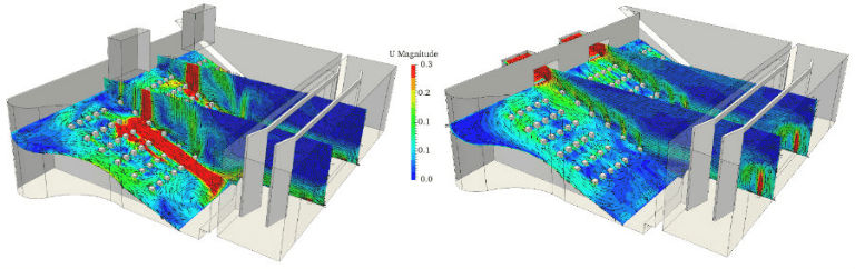
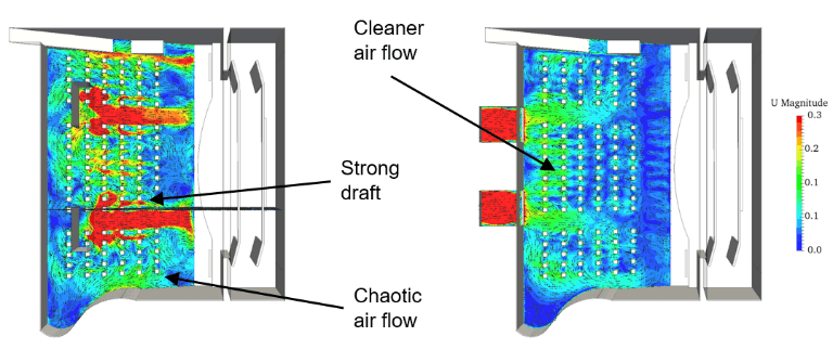
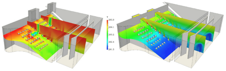
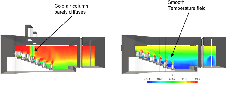
CFD simulation allows us to analyze the detailed aspects of both designs by visualizing the airflow velocity and direction, the air temperature, and the effective draft temperature (EDT), which combines the velocity and temperature information.
Air velocity
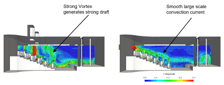
Very strong drafts can be observed in the occupied region of the first design. The flow from the inlets is very poorly distributed through space, and the flow around the occupants is dominated by small-scale erratic vortices. The second design, however, reveals no strong drafts near occupants and a relatively large convection current renewing air near the occupied area.
Measured against the standard, the first design breaches the 0.15 m/s draft limit across much of the seating at temperatures below 22.5 °C.
Temperature
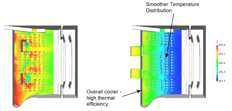
The simulation revealed large temperature differences throughout the occupied region, with some occupants getting exposed to very cold air. The thermal efficiency is also poor, as evidenced by relatively warm air. In the second configuration, all occupants are within the temperature comfort region, and the air temperature shows greater stratification.
EDT
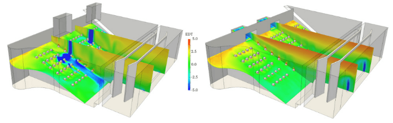
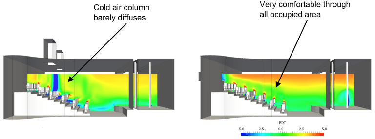
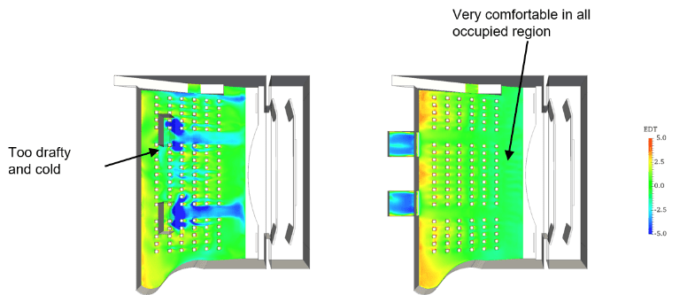
In the first design, a large number of occupants find themselves outside the comfort standard (-3°F < EDT < +2°F). On the other hand, no discomfort can be observed for any occupant location, and occupants are well within the comfort limits.
Case study conclusions
The first design has strong drafts near occupants and large temperature differences across the seating, with many occupants outside the comfort zone and the area directly under the inlets the worst of it. The second design removes the drafts and the large gradients. A few changes to inlet and outlet placement improved thermal comfort substantially, and the whole study took a few hours of manual and computational time.
Conclusion
Simulation predicts thermal comfort at the design stage with an accuracy hand calculations cannot reach, and it is the only practical way to catch local discomfort and size ventilation correctly before anything is built. That makes HVAC simulation part of the design and construction engineer’s toolkit rather than a specialist add-on.
Assessing a design against ASHRAE 55 may well show that comfort cannot be guaranteed everywhere in a space, and the answer depends on the clothing and activity profiles you expect. That is an acceptable outcome; it just has to inform how areas get allocated to different uses. Satisfying everyone is not achievable. The standard is built on laboratory and field study data and provides a statistical framework, not a guarantee.
Frequently asked questions
ASHRAE stands for the American Society of Heating, Refrigerating and Air-Conditioning Engineers. It is a global professional body founded in 1894 that publishes standards for building systems, energy efficiency, indoor air quality, and thermal comfort.
ANSI/ASHRAE Standard 55-2023 is the current edition. It supersedes 55-2020 and incorporates eleven addenda, including a new vertical air temperature gradient method and metabolic rate coverage extended to 4 met.
ASHRAE 55 was first published in 1966. Editions have followed in 1992, 2004, 2010, 2013, 2017, 2020, and 2023, with addenda issued between full editions under a continuous maintenance process.
ASHRAE 55 defines thermal comfort as “that condition of mind that expresses satisfaction with the thermal environment”. It depends on six factors: air temperature, mean radiant temperature, air speed, humidity, metabolic rate, and clothing insulation.
Four environmental factors (air temperature, mean radiant temperature, air speed, humidity) and two personal factors (metabolic rate in met, clothing insulation in clo). ASHRAE 55 requires all six to be accounted for in combination.
The comfort zone is the set of operative temperature and humidity combinations acceptable to at least 80% of occupants, at a stated air speed, clothing level, and metabolic rate. It is plotted as a polygon on a psychrometric chart and moves whenever those assumptions change, which is why the standard specifies no single temperature range.
Compliance rests on three things: whole-body comfort within PMV -0.5 to +0.5 and PPD at or below 10%, absence of local discomfort from draft, vertical temperature gradients, floor temperature and radiant asymmetry, and documentation of the assumed clothing, metabolic rate, and design conditions.
No. It is a voluntary consensus standard. It becomes enforceable only when a project specification, a green building code such as ASHRAE 189.1 or the IgCC, or a rating system such as LEED or WELL references it.
The standard method uses the Fanger PMV/PPD model and applies to mechanically conditioned spaces. The adaptive method ties the acceptable indoor temperature to the prevailing mean outdoor temperature and applies only to naturally conditioned spaces with occupant-operable windows, at 1.0 to 1.3 met and 0.5 to 1.0 clo, when outdoor temperatures are between 10 and 33.5 °C.
Other thermal comfort resources from SimScale
- Whitepaper: Simulating the Indoor Environment
- What is PMV and PPD?
- ASHRAE 55 and ISO 7730 compared
- What is EN 16798?
- Thermal Comfort and Radiation with SimScale
- Radiation and Thermal Comfort for Indoor Spaces
- Ensuring Thermal Comfort with HVAC for a School Building Design: Case Study Ramboll
- How to Comply With EN 15251 and EPBD
- Indoor environment simulation