As temperatures rise across the globe and people are working for longer hours through the day, the need for a comfortable working environment and to improve thermal comfort has increasingly grown. More electronics means additional heat in an interior space. The result is that the modern work environment has driven a rapid increase in the necessity of air cooling and conditioning in these occupied interior spaces.
In spite of the advancements in air conditioning technology, thermal comfort in offices seems like a far-fetched dream. There are always employees who feel it’s too hot and open the windows while few others warm themselves with two pullovers in the neighboring cubicles. It is every employee’s dream to find a thermally optimal spot in an office. For example, recent studies show that women in workplaces feel on an average 3°C, colder than men. This has been primarily attributed to different metabolic rates. Thus, designing workspaces by recognizing the need for diversity can significantly improve employee satisfaction and enhance workspace dynamics.
A hand-waving argument used by the HVAC industry for the determination of the size of the cooling system needed (in BTUs) to improve thermal comfort in a room with a roof height of 8 feet has been square foot x 25 + 1000 x windows + 400 x persons. However, this equation significantly neglects the modifications that are made in office spaces to accommodate cubicles, heating from computers and other electrical appliances in the microenvironment. In addition, it also disregards the effects of exposure and orientation of windows, shading, etc.
SimScale offers an effective cloud-based simulation tool for the design of office space architecture that can be used by HVAC designers, civil engineers, and architects alike to optimize workspaces and improve thermal comfort. Simulations can provide a better estimate of the size of the HVAC systems required for a specific environment. They also facilitate the strategic mapping of optimal positioning for the systems to minimize energy costs. Here it’s important to note that six major factors have been identified to define the concept of thermal comfort. Of these six, four constitute environmental factors while two are personal. The two personal factors are, of course, beyond the control of designers. However, the four environmental factors should definitely be considered during the preliminary design phase. The four environmental factors affecting thermal comfort are:
- Air temperature: temperature of the air in the room
- Air velocity: air movement can cause heat transfer from the body surface, smaller velocity implies less loss of heat
- Radiant temperature: heat loss occurs not only by convection but also by radiation
- Relative humidity: humidity in the microenvironment can also significantly affect living conditions
Two personal factors influencing thermal comfort, which the designer cannot influence, are:
- Clothing: can be moderately controlled by the individual
- Metabolic rate: a factor that is beyond anyone’s control
Simulations using SimScale can be used for preliminary design and testing of innovative solutions such as underfloor heating (or on the roof) and passive instead of active cooling systems. In this article, we will discuss some aspects that need to be considered in the early design and testing phases and show small examples demonstrating the effects of these external conditions on thermal comfort.
Thermal Comfort in the Office Primary Aspects to Be Considered
The optimization of air conditioning to improve thermal comfort requires the use of thermal simulation. At the very least, it must also consider other primary aspects like the infusion of fresh and removal of stale air, heating infusion due to electronics, the seating position of employees, cubicles or separating partitions, exposure to outer environments (through windows and doors), insulation through walls, etc. Some important aspects to consider when designing an air conditioning or ventilation system for an office space are:
-
Placement of Inlets and Outlet Points
It is generally understood that hot air rises, while cold air settles down, displacing the hot air that originally sat there. However, the placement of the inlets and outlet ducts could prove quite consequential. Placing an outlet duct in the opposite direction can significantly increase the turbulence (or internal air velocity) in the space. Finding an optimal location and direction for inlet and outlet ducts could significantly reduce the energy costs related to removing the hot and stale air in the internal environment.
-
Exposure and Orientation of Windows
Most workspace walls are considered well-insulated and generally, maintain a constant temperature. However, depending on the orientation of the windows (facing either North or South), it could important to consider not only the amount of sunlight exposure but also the heat addition as a result of this orientation. Office spaces with South-facing windows receive significantly more sunlight heat compared to those with North-facing windows.
The average sunlight, over a 24-hour period, on a global scale, is about 164 Watts/Sq m. However, this varies significantly based on the latitude and longitude of the location. Knowledge of the location can provide a seasonal estimate of the amount of heat generated from sunlight. For example, around 40 degrees N latitude (Munich is around 48 degrees N), the average heat is 600 W/Sqm in summer, while only 300 W/Sqm in winter. This can strongly affect both the performance of the heating and cooling system and the internal conditions of the workplace.
Sunlight exposure can be slightly modified and controlled through the clever design and construction of window structures. Design features, such as the depth of their placement, can reduce direct sunlight exposure due to the shadow of the structure.
-
Insulation of the Walls and Roof
Generally, most of the internal walls are wooden and lightly insulated. In colder countries, the outer walls are significantly more insulated. Hence, the internal and external walls can be differentiated based on their insulation types. The internal walls can be thinner, facilitating heat transfer across rooms, constant heat flux, or a zero temperature gradient. The external walls can be considered to be of constant temperature, allowing slight heat transfer. In addition, depending on the placement of the office in the building, the roof could also be considered a constant temperature source, therefore further facilitating heat transfer in the environment.
-
Presence of Electrical Appliances
The heat transfer from the electrical appliances can be modeled as a natural convective process. For the steady state, they can be considered as a constant temperature source.
In addition, several other aspects, like the effects of a courtyard, external shading due to trees, a fountain in the courtyard, etc., can always be strategically added. These features affect the overall thermal comfort. As a simple prototype, a convective heat transfer analysis of the SimScale office space is considered and discussed below.
Download this case study for free to learn how the SimScale CFD platform was used to investigate a ducting system and optimize its performance.

Thermal Comfort in the Office How to Improve Thermal Comfort with SimScale
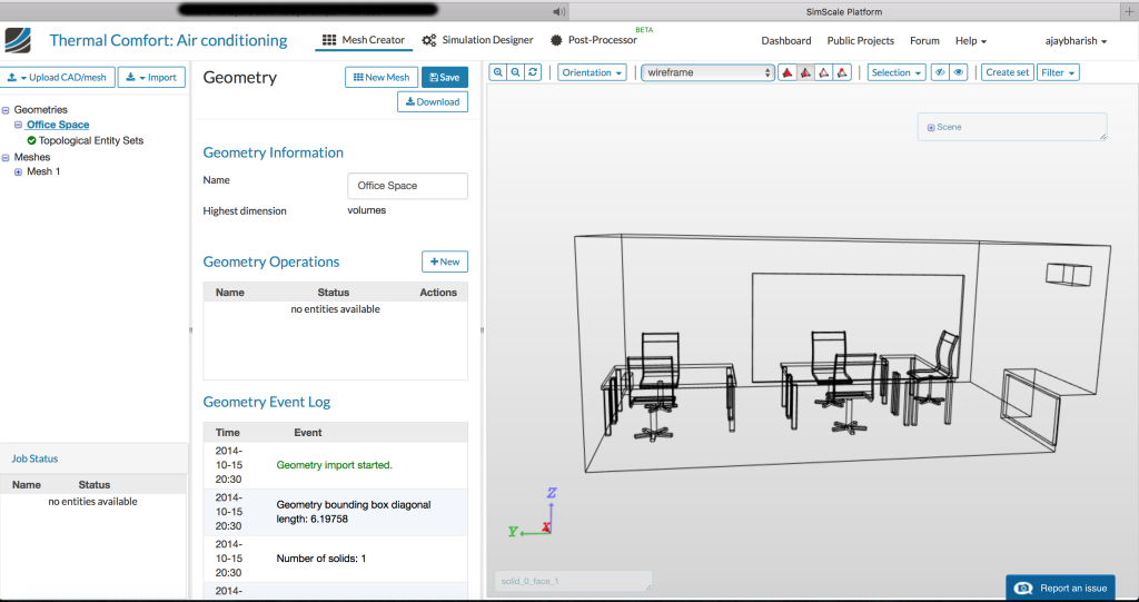
This public project on SimScale provides a template for starters who intend to use SimScale to design their HVAC system. It also provides a thorough understanding of how you can improve thermal comfort in an office space. The template is based on a part of the old SimScale office. Thus, for designers, it is not necessary to start from scratch but one could directly modify the template for their usage. In this article, we demonstrate the applicability to modify this public project template to visualize the effects of varying conditions that are commonly encountered during the design process. The modified version of the project, for the conditions described below, can be found in the library of public projects.
The scenario considered is a hot summer day when the outside temperature is about 30 °C. The effect of cooling systems is investigated. The cooling system has a passive outlet and an active inlet. A more detailed tutorial on setting up a similar problem can be found in this recorded webinar: “Thermal Comfort of a Living Room“. The two earlier webinars on the same direction of air cooling and ventilation can also be found here and here.
The above CAD model is meshed using a hex-based mesh suitable for internal flow with a fineness at level 3 and computed over 16 cores. This results in a total of 1,506,294 nodes and 1,326,342 volume elements. A natural convection heat transfer process is chosen. For a preliminary design analysis, it would be sufficient to assume that the flow is laminar and has reached a steady state. In reality, HVAC designers only need to consider the steady state rather than the initial transient state. Thus, the model described here is as near to reality as possible.
The material properties for air are imported from the SimScale library. The initial velocity is zero while the pressure is atmospheric pressure. The initial temperature in the room is set at 30 °C. The conditions of the room after approximately 15 minutes (1000 sec) is reviewed and discussed.
The customizations can begin at the assignment of the boundary conditions. We compare two simple scenarios to start with. In the first case, the inlet for colder air is above, while a passive outlet (outlet at atmosphere pressure) is provided at the bottom. In the second case, they are exchanged. In each of these cases, the walls are considered to be adiabatic or do not otherwise conduct.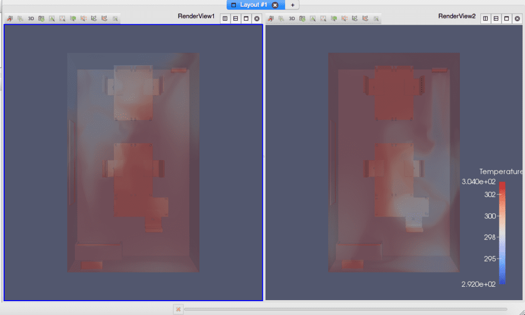
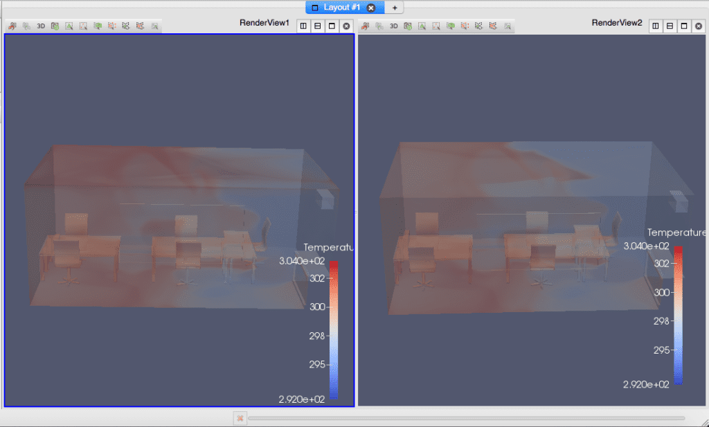
Figure 2: Comparison of the temperature profiles for variations in placement of inlets/outlets. Inlet is on top (and outlet on bottom) and is shown on the left while the opposite is on the right
Figure 2 shows the comparison of the final temperature, with the first case on the left and the second on the right. Though they appear to be nearly similar, the second case is a little better than the first. However, when comparing the velocity profiles in Figure 3, it is quite evident that the first case facilitates better air circulation, in addition to slightly higher air velocities in the room. Overall, it can be concluded that the second case shows more promise.
Continuing with the customizations, consider the second case. In this instance, a different boundary condition is considered for the roof. For example, if the office was on the top floor, and we maintain the assumption that the roof is badly insulated, then the roof can be almost as warm as the outside conditions on a hot summer’s day (say 30 °C). This is quite a challenge in our endeavor to improve thermal comfort.
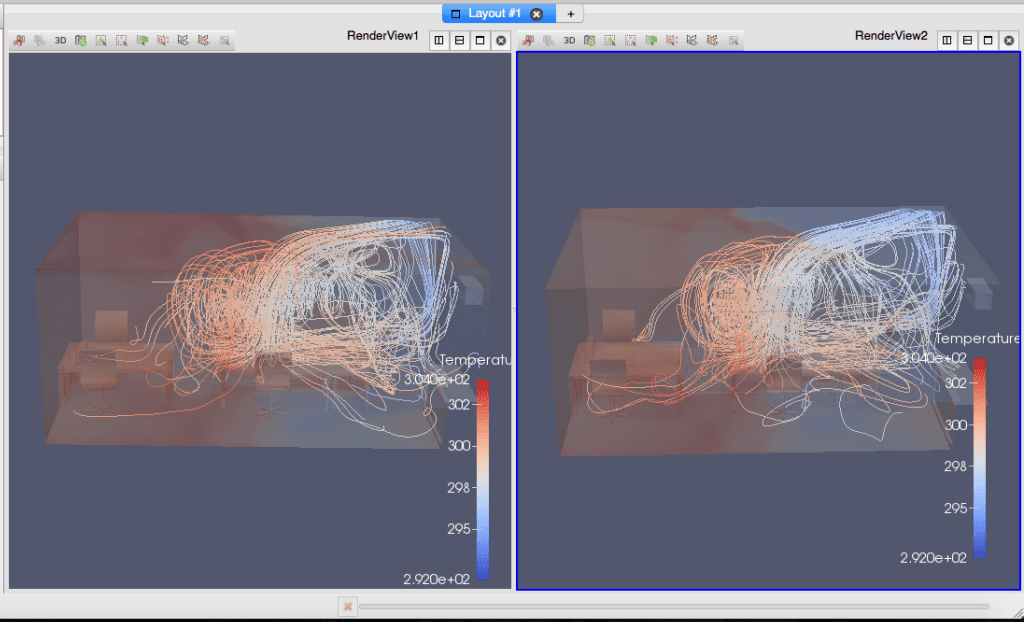
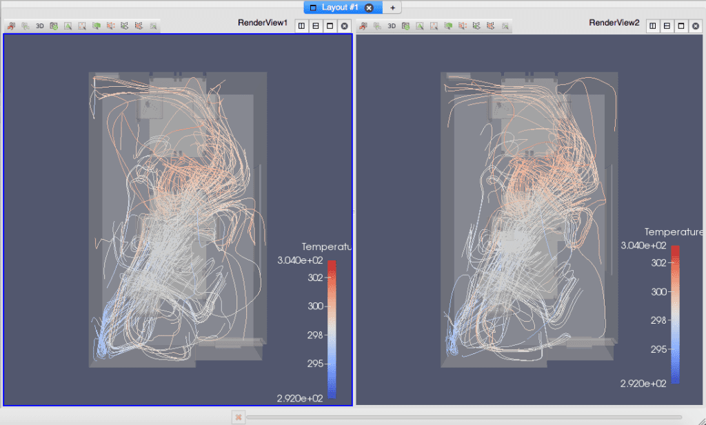
Figure 4 shows the variation of the temperature profiles. Case two, with all walls (including roof and floor) adiabatic, is still on the right. The third case, where the roof is heated up, is illustrated on the left. As expected, there is a strong counter-current from the roof that is heating the room.
The temperature distribution is different but the streamlines, shown in Figure 5, demonstrate a strong heat wave due to the temperature of the roof which is slowing the speed of heating of lower and far-end areas of the room. This is a common experience of most people living on the top floor. This is why it’s important to improve thermal comfort in these situations.
Instead of the roof, what if there was a not-so-well insulated outer wall or a wall made of glass? In this scenario, a constant temperature boundary condition is assigned to this wall. The comparison for such a scenario is as shown in Figure 6. Contrary to the assumption that this could impede air cooling, such a scenario actually facilitates better cooling by increasing the flow of air across the room.
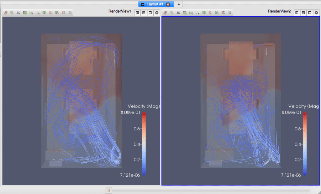
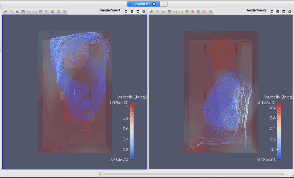
Finally, the last case is regarding the orientation of the window. Generally, offices with windows facing South receive much more sunlight and heat compared to those facing North. For example: In Munich, the orientation of the sun, on an average, is at 64 degrees in summer, 18 degrees in winter, and 41 degrees in spring. Thus, the offices with windows to the South, receive an enormous amount of heat in summer compared to cooler offices with windows to the North. This example is considered just to illustrate this difference. Figure 7 shows the contrasting velocity profiles in the two different orientations.
The cases discussed above are by no means exhaustive, but provide a brief glimpse of the possibilities of the applicability of such simulations using SimScale in HVAC. Such simulations can be used to obtain better customized cooling systems, and provide optimization solutions to help improve thermal comfort and energy efficiency.
This free infographic illustrates how architects and engineers can use CFD to virtually test and optimize building designs and HVAC systems. Download it for free.