The rising demand for renewable energy has increased interest in harnessing the abundant wind energy around us. Wind turbines are at the forefront of utilizing this energy as they provide a long-term, cost-effective, and low-maintenance solution for the conversion of wind energy into electricity.
It is, therefore, crucial to ensure that wind turbines are designed optimally for their specific operating conditions to extract the maximum possible amount of energy. In this article, we discuss how wind turbine design can be enhanced and accelerated with simulation using CFD and FEA tools to achieve optimal efficiency and performance.
Wind Turbine Design
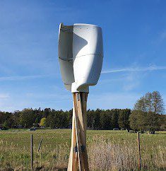
There are essentially two types of wind turbines, horizontal-axis wind turbines (HAWT) and vertical-axis wind turbines (VAWT). These are turbines where the rotation of the turbines is parallel and perpendicular to the ground, respectively. The vast majority of wind turbines in use today are horizontal-axis types as they have proven to be more efficient than the vertical-axis types.

Betz Limit and the Extracted Wind Power
The theoretical maximum efficiency of a wind turbine is 16/27 or 59.3%, as determined by German physicist Albert Betz in 1919. In other words, only 59.3% of the kinetic energy from wind can be captured by a perfectly designed wind turbine in open flow that experiences no losses in operation. This theoretical maximum is known as the Betz limit, and all wind turbines are designed to approach this limit to the greatest extent possible. Betz law demonstrates that “The power extracted from the wind is independent of wind turbine design in the open flow. Therefore, it is impossible to capture more than 59.3% of kinetic energy from the wind” [1].
The output power of a horizontal wind turbine blade can be derived as follows:
$$ P = \frac{1}{2} \rho A V^3 $$
where
- \(\rho\) is the air density (\(kg/m^3\))
- \(A=\pi R^2\) is the rotor’s surface area (\(m^2\))
- \(V\) is the velocity of incoming wind flow (\(m/s\))
How Much Can A Wind Turbine Produce?
According to Wind Europe, formerly known as the European Wind Energy Association, an average onshore wind turbine can produce 6 million kWh over the span of a year, while an average offshore wind turbine can produce more than double this power. This is not the maximum output these turbines are capable of and is rather a function of the amount of wind energy available for conversion.
Turbine Blade Design
The design of wind turbines has largely to do with the design of the turbine blades. These blades are designed to maximize the transference of the kinetic energy from the wind to the blade from a specific direction known as the angle of attack to facilitate the continuous rotation of the turbine. The optimal angle of attack for a wind turbine lies between 25° to 35°.
The most important considerations in the design of wind turbine blades are outlined below:
1. Wind Turbine Materials
The materials used to manufacture the wind turbine blades have to satisfy certain physical requirements for their operation. They have to be lightweight to turn faster. They have to have high strength, high stiffness, resistance to fatigue, and weather resistance to be more durable and able to withstand the adverse effects of the elements of nature.
2. Number of Turbine Blades
The number of blades on a wind turbine plays an important role in its efficiency. Most horizontal-axis wind turbines have 2 or 3 blades, and this is for good reason. The more blades a turbine has, the greater the torque it can generate, but the slower it rotates due to increased drag from wind resistance. Turbines with one or two blades will theoretically achieve a higher efficiency due to significantly reduced drag. However, they will be much less stable and will experience high vibration. This instability may lead to damage over the long term. Nevertheless, having more blades on a turbine is more expensive not only because of the extra blades that need to be manufactured but also because the supporting tower has to be built stronger. The ideal number of blades for a horizontal-axis wind turbine has thus been generally accepted to be 3 blades to satisfy the requirements for efficiency, durability, and high performance [2].
3. Wind Turbine Blade Shape
The shape of wind turbine blades must have an aerodynamic profile that enables them to rotate as the wind impacts them from a variety of angles. They have a similar curved design to the wings of airplanes, known as airfoils. The curved blade causes a pressure differential between the air that flows over the blade (which flows faster) and the air that flows under it which is what causes lift and the blade to rotate. The most efficient wind turbine shape will be able to be suitably impinged by oncoming air but also minimize drag. To achieve this, turbine blades are usually twisted along their length and taper down in width towards the tip.
4. The Tip Speed Ratio (TSR)
The tip speed ratio (TSR) is defined as the ratio of the speed of the tip of the turbine blade to the speed of the wind. It is an important parameter in the design of wind turbines as it is proportional to their performance. The TSR is dependent on the shape of the wind turbine, as well as the number of blades it has. Generally, the optimal TSR lies between 7 and 8 for most three-blade horizontal-axis wind turbines, but it may vary depending on the specific design [3].
In a nutshell, a well-designed wind turbine should be sturdy, stable, durable, and with blades that are capable of capturing most of the wind’s energy with an optimized TSR for power generation.
Wind Turbine Simulation using CFD and FEA
The parameters that govern the performance of wind turbines can be deconstructed into numerical values, equations, and CAD models, which can be fed into simulation tools as data or boundary conditions. The effects of these parameters can then be quantified and visualized as the simulation is run, and the necessary adjustments can be made to optimize the design. Computational Fluid Dynamics (CFD) and Finite Element Analysis (FEA) tools are crucial in this process.
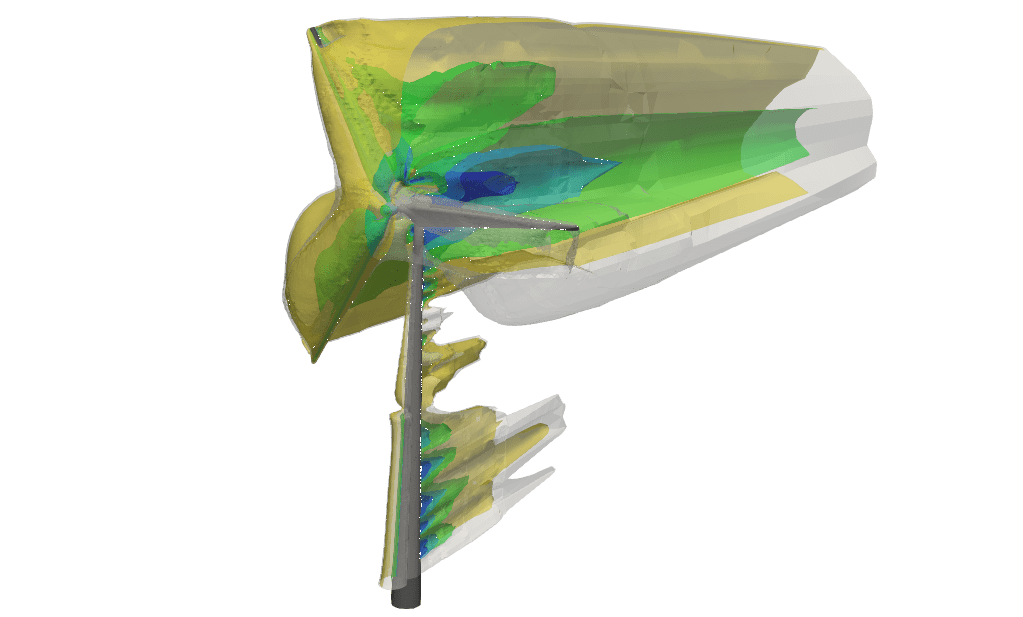
CFD Simulation of Wind Turbines
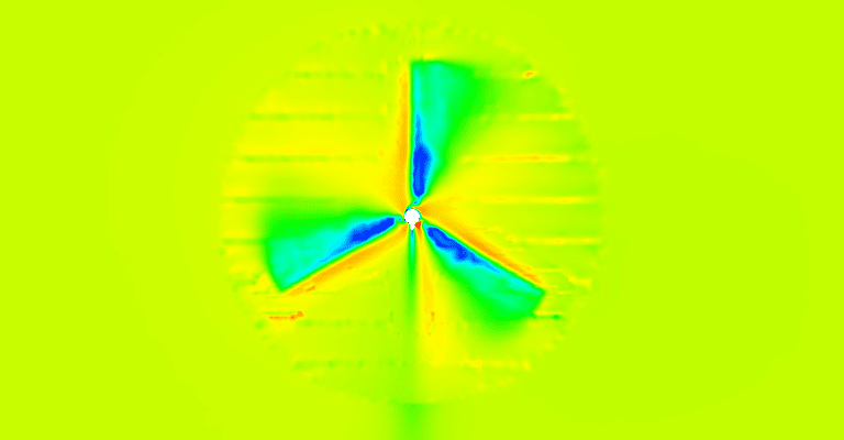
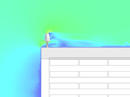
Computational Fluid Dynamics (CFD) is a numerical analysis tool that allows engineers to study the flow of air (and fluids in general) around and through objects such as the blades of a wind turbine. The data on wind is usually known and is generally predictable from information obtained from field studies. The idea is to translate this information into usable simulation data for analysis.
The information may include parameters such as inlet and outlet velocities, pressures, temperatures, etc., that specify the state of the fluid at the edges of the simulation domain. This allows engineers to easily vary the properties of the simulated wind and study how the wind turbine would behave under different conditions.
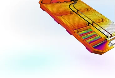
FEA Simulation of Wind Turbines
Finite Element Analysis (FEA) is also a numerical analysis tool, but it is used instead to investigate the physical properties and shape change of an object by analyzing its structural integrity and mechanics. This allows engineers to minimize their need to create physical prototypes of the design, at least until sufficient testing and adjustments are made virtually.
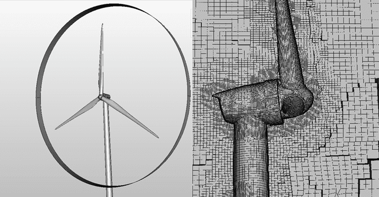
Engineers create 3D models of the wind turbine components (namely its rotor, hub, nacelle, and tower), and through the use of advanced algorithms, these geometrical shapes are divided into smaller elements collectively called a mesh. The finer the details of these models via proper meshing, the more accurate and reliable the simulation of the fluid dynamics and structural behavior would be. Upon meshing, FEA simulations can be performed to analyze displacements, forces, and pressures on the turbine blades and other parts.
CFD and FEA are used in tandem to analyze the performance of a wind turbine model. In simple terms, FEA simulates the physical structure of the turbine, and CFD simulates the fluid flow around it. The designing aspect comes mostly from the FEA simulation, where the turbine material, shape, and size may be adjusted to achieve optimal results.
After completing the simulation, the results are analyzed to evaluate the performance of the wind turbine design. The amount and quality of data for analysis depends on the quality of the simulation as well as the quality of the geometry creation and physics setup. At this stage, small changes can be made to these factors, and the simulation is run again to determine if any improvements in the simulation results can be achieved.
Cloud-Native Simulation for Industrial Machinery Manufacturing
Our latest eBook explores how cloud-native simulation is transforming industrial machinery manufacturing challenges into opportunities. Download it for free by clicking the button below.

SimScale for Wind Turbine Simulation
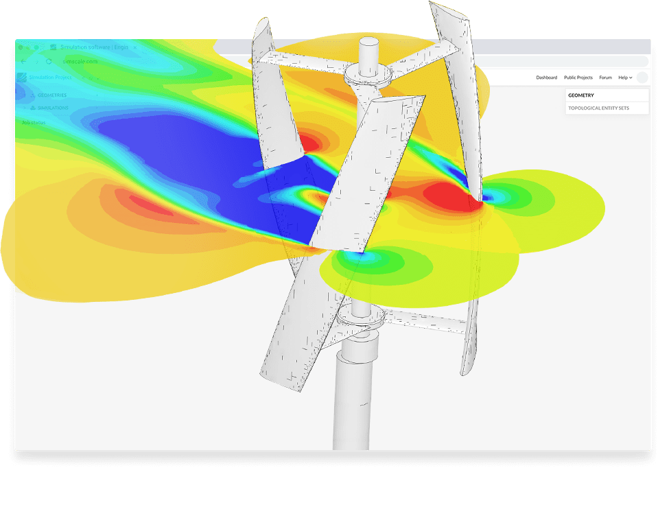
To determine the characteristics of a wind turbine design, engineers must conduct tests on various environmental factors that will naturally vary in real-world conditions, like air speed and temperature. This can be accomplished using online computational fluid dynamics (CFD) simulations through platforms like SimScale. SimScale provides cutting-edge technology in the field of engineering simulation in a wide range of engineering fields, including rotating machinery like wind turbines.
The primary focus of such simulations lies in examining the design of the wind turbine blades and experimenting with different design variations to find the optimal design for the desired outcome. For instance, flat blades, which are one of the oldest blade designs still in use today, are losing popularity due to reduced rotational efficiency caused by wind resistance during the upward stroke- which is why they are referred to as drag-based rotor blades. Nevertheless, flat blades are cost-effective to manufacture, straightforward to replicate in terms of shape and size, and require less specialized expertise for implementation.
Whether it is flat blade designs or curved blade designs, there is room for improvement through online simulations and the evaluation of various design iterations. This encompasses testing different materials using CFD and FEA simulations, exploring variations in length and width, and assessing performance in different seasonal and environmental conditions. SimScale is a valuable tool for users to optimize their wind turbine designs by simulating them at various air velocities in parallel. For example, check out the following wind turbine simulation projects:
In fact, there are several reasons why using Simscale can set you and your wind turbine design project apart, some of which are elaborated below:
Cloud-Native Computing for Wind Turbine Simulation
Due to its cloud-native nature, SimScale enables engineers to run multiple simulations simultaneously instead of one after another, reducing the time required for design iterations. Users do not need to worry about expensive hardware, complex installations, or limited resources. SimScale’s cloud-native platform enables engineers and designers to bypass these issues and simplifies the simulation process down to a simple “sign-in and simulate directly in your browser” type of process. The application of such simulation tools, along with the power of cloud-based computing technology, makes it possible to cut simulation times down from days to mere hours, allowing engineers to complete more design cycles in a given time frame
Advanced CFD and FEA Technologies
Simscale offers CFD simulation with a mix of the best open-source and proprietary CFD solvers, which have been seamlessly integrated into the SimScale interface. These solvers can cater to the simulation of compressible and incompressible flow as well as laminar and turbulent flows with turbulence models, such as LES Smagorinsky, SST-DDES, k-omega SST, and k-epsilon.
The SimScale FEA tool allows for the simulation of an object’s response to static and dynamic loads as well as vibrational analysis to determine the rigidity and durability of the object. With
SimScale’s cohesive ecosystem of simulation products, you can optimize both the FEA and CFD components all in the same place and in real time, allowing for virtually endless iterations of simulation runs to achieve the best results possible.
Lower Cost and Faster Time-to-Market
The entire purpose of engineering simulation is to minimize the cost of physical prototype building and testing. The reduced cost associated with traditional simulation is even more pronounced with SimScale due to the added efficiency of cloud-native computing. With SimScale, the costs of expensive hardware and software licenses are eliminated. Quicker innovation can be achieved with better resource management in the research and development phase, which ultimately leads to faster time-to-market.
Seamless UX and Proven Workflows with CAD Software
SimScale empowers engineers to innovate faster and enables users not so familiar with the intricacies of engineering simulation to still take advantage of the resource through a simplified and guided simulation process reinforced by a dedicated, real-time support team and a user-friendly interface. Experienced engineers can easily navigate SimScale’s interface from start to finish with little to no help, and it takes an inexperienced user little time to become adept, especially after following the plethora of guides, tutorials, and educational content.
SimScale’s online post-processer renders results in easy-to-understand and highly detailed formats that can allow the user to compare and evaluate an array of useful output data, capture images and animations, and more. Running wind turbine simulations online and applying design changes directly on the spot is possible with SimScale via your web browser without the need to install any specialized software.
SimScale also has seamless integrations and proven workflows with multiple CAD software, enabling users to design, modify, and update their CAD designs, which would automatically update in SimScale so that they can run simulations in a more streamlined and efficient manner, thanks to the power of CAD associativity.
Case Study: Energy Machines Use SimScale to Optimize Wind Turbine Designs
Simulation is indispensable for the design of wind turbines, and Simscale is a state-of-the-art resource that engineers can use to run their simulations to the highest degree of accuracy and speed. With the unparalleled power of cloud computing, SimScale’s easy-to-use interface, and live expert support to guide you, your wind turbine simulation can be performed quicker, more accurately, and more efficiently than ever before.
Here’s what the engineers at Energy Machines, Danish service providers of integrated energy systems, said about using SimScale in their design of vertical-axis wind turbines: “Being able to run many simulations in parallel on the cloud has been very useful and saved us a lot of time. Using SimScale has reduced our wind turbine testing by weeks. By simulating on the cloud with more cores than on a personal computer, we have been getting results about 3x quicker than if we run it locally, as before. We also save time on how quick it is to set up many similar simulations by duplicating and changing geometry or other input parameters.” Read more about how Energy Machines optimize wind turbine designs with engineering simulation in SimScale.
References
- Jayanarasimhan, K. and Subramani-Mahalakshmi, V. (2022). Wind Turbine Aerodynamics and Flow Control. Wind Turbines – Advances and Challenges in Design, Manufacture and Operation. IntechOpen, Oct. 26, 2022. doi: 10.5772/intechopen.103930.
- Kehinde Adeseye Adeyeye et al (2021) IOP Conf. Ser.: Earth Environ. Sci. 801 012020
- Yurdusev, M. A., Ata, R., & Çetin, N. S. (2006). Assessment of optimum tip speed ratio in wind turbines using artificial neural networks. Energy, 31(12), 2153-2161.