As you know, here at SimScale we are continually updating our platform, and adding new features along the way; and because it’s all in the cloud our users benefit from immediate access. Check out our roadmap here for more information. This fall season, we’ve been quite busy with the release of our API integration and the Beta release of our new post-processor, but we’ve also been busy with additional enhancements. In this blog, we’ll walk you through seven of our recent updates and feature additions.
1) New Feature: Radiation for Conjugate Heat Transfer v2.0
The development of this feature is important for electronics cooling in natural convection, where there can be a significant temperature difference between solids and the air. Once larger differences are present, radiation starts to have a significant impact. For this specific feature, surfaces are considered either completely transparent or opaque (grey body). The surface to surface radiation approach is based on the discrete ordinate method (DOM), which provides a domain discretization in angular variables, hence providing a discrete representation of radiative directions.
How to Use This Feature:
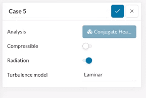
In order to enable radiation, the user will need to activate the “Radiation” toggle in the simulation option (see picture below).
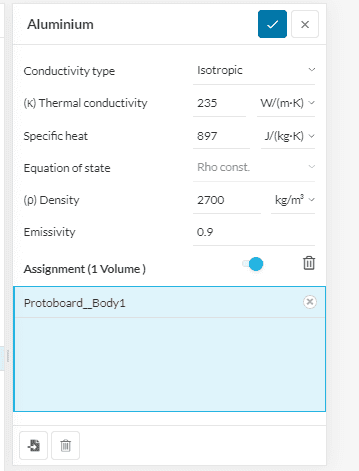
When the user assigns solid materials, they will find a new field for the emissivity (see picture below). The emissivity is already provided for the specific material selected by the user, however it can be changed if further customization is required.
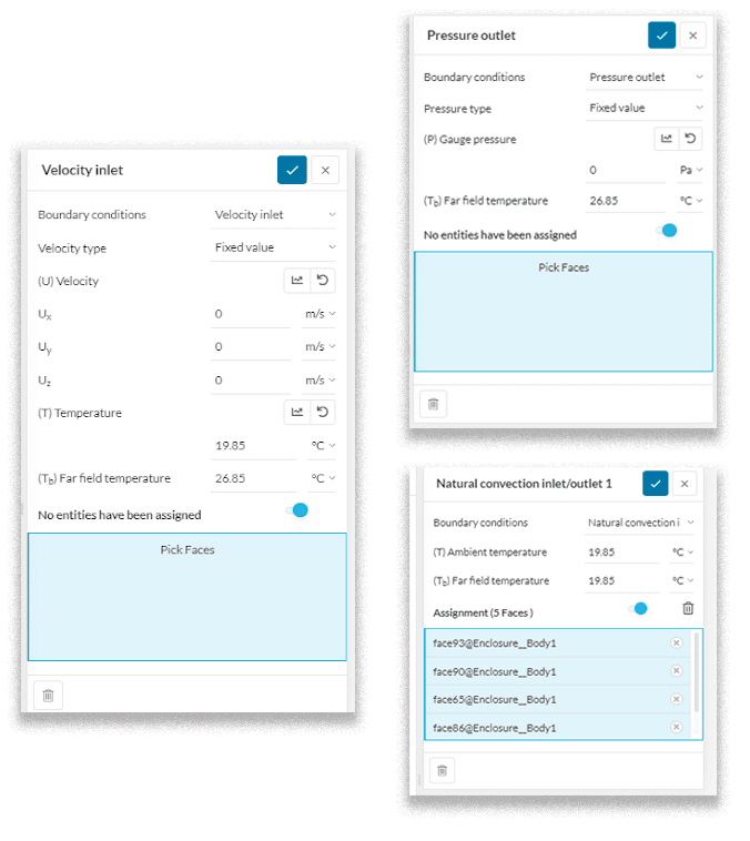
Then, the user will find a new field also for the boundary conditions. In particular, for “velocity inlet”, “pressure outlet”, and “natural convection inlet/outlet”, the “far field temperature” will need to be specified (examples in below images).
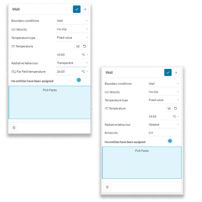
For the “Wall” boundary condition (used to model a solid that isn’t present in the analysis) the radiative behaviour has to be set as either:
- Opaque (typical grey body): the user must also also specify the emissivity of the selected wall.
- Transparent (typical glass window): the user must specify the far-field temperature.
For radiative heat transfer problems, further settings can be changed within the numerics, as shown in the picture below. Most importantly, the radiation resolution can be changed. This affects the discretization of the directions for which the radiative problem is solved. The settings are coarse, moderate and fine. Increasing the radiation resolution will lead to a higher number of directions and hence improved angular discretization of the radiative problem (usually a more accurate result).

2) New Feature: Thin Layer Resistance for Conjugate Heat Transfer v2.0
This feature allows users to describe the thermal behavior of very thin layers of material, such as thermal paste, or coatings on electronics components. These thin layers would need a very fine mesh to capture and so it is more efficient to simply model a surface. The interface is given an additional resistance value, which affects the heat transfer as if it were a solid: all the heat going through the thin layer will result in a temperature gradient.
How to Use This Feature:
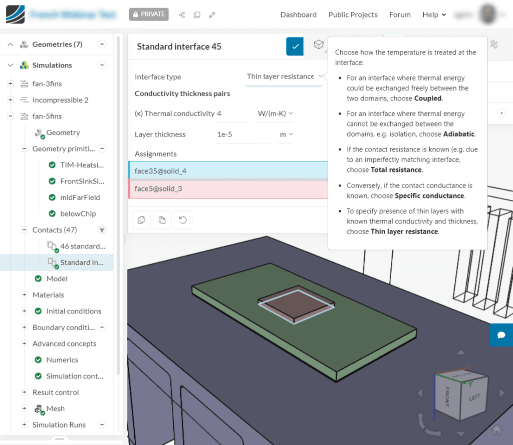
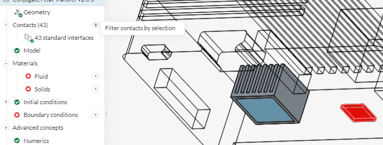
Thin layer resistances are set up in ‘contacts’. The user has to select the targeted interfaces within the domain and click on “Filter contacts by selection” (see picture below).
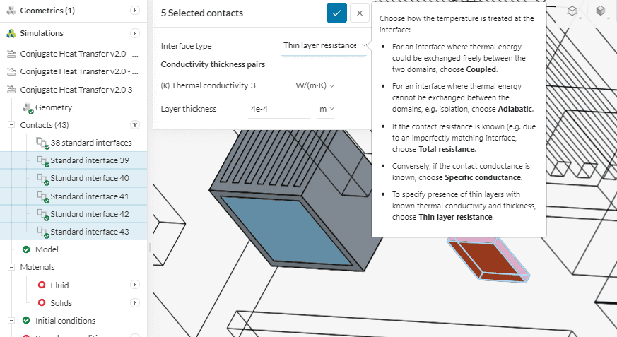
Next, the user will select the “thin layer resistance interface” option for the Interface type, and then they can input the thermal conductivity and the layer thickness for the specific selection (see picture below).
This paper addresses the difference between on-premises software and SaaS
solutions for computer-aided engineering, explaining how SaaS came to be and its
key benefits.

3) Product Update: Mesh Visualizer Performance Optimization
Our mesh quality visualizer now provides a significant boost in loading performance that will allow you to visualize your mesh much faster than ever before.
The mesh quality visualizer provides advanced functionality to generate detailed analyses for a variety of mesh related metrics. This includes aspect ratio, non-orthogonality, volume ratio, edge ratio, and minimum edge length. The ability to rapidly configure legends and set up cutting planes makes it easier to get an understanding of your mesh before a simulation is prepared.
How to Use This Update:
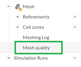
To access the mesh quality visualizer, simply click on the “Mesh Quality” option under the ‘Mesh’ section (as shown in the image below). The visualizer will take a few moments to load after which you can perform your mesh interrogation.
4) Product Update: Volume Refinement with the Standard Mesher
Continuing our efforts to make the standard mesher more robust in a variety of applications, local refinements have now been improved to allow the user to select existing volumes as refinement regions, in addition to the ability to create and use primitives as refinement regions.
How to Use This Update:
While defining the region refinements for the standard mesher, simply select the volumes to be refined when prompted. Specify the maximum cell size, and the mesher will ensure that the refinement is applied entirely to the selected volumes.
The following short video illustrates the functionality using an assembly comprising multiple rivets which may need to be refined.
5) New Feature: PCB Material – FR4
It is now possible to assign a specific material, FR4, for PCB components. This new feature allows the user to assign cross-plane orthotropic conductivity for Conjugate Heat Transfer (CHT) simulations of electronic components.
How to Use This Feature:
FR4 conductivity is defined as cross-plane orthotropic. In the material panel it is possible to specify the in-plane conductivity (isotropic conductivity) and the cross-plane conductivity which is defined normal to the in-plane. Moreover, the orientation of the conductivity can be specified depending on the chosen reference system:
- Cartesian: the cross-plane conductivity is defined along the Z-axis as per the global reference frame.
- Custom: the cross-plane conductivity can be arbitrarily defined using unit vectors, and the resulting orthogonal plane is the one on which the in-plane conductivity acts.

Download our ‘Tips for Architecture, Engineering & Construction (AEC)’ white paper to learn how to optimize your designs with cloud-based CFD!

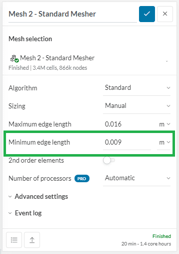
6) Product Update: Standard Mesher (Manual) Minimum Edge Length
The standard mesher is in a phase of constant evolution and improvement, and the addition of the ability to specify a minimum edge length for a manual mesh generation is another step in the direction of making the standard mesher a more robust meshing solution.
Previously, users only had the ability to specify a “Maximum Edge Length” for the standard mesher, but with the deprecation of the Tet-Dominant mesher (which had the ability to enter a minimum edge length), and requirements coming in from customers to support this, we have developed and rolled out this functionality to all users.
It is important, however, to understand that the specification of the maximum edge length and the minimum edge length are in no way strict numbers that the mesher will try to enforce in all scenarios, since there can be a multitude of situations where adhering to those limits would not be optimal and may even generate a sub-optimal mesh. These parameters only provide the user with the ability to define bounds within which the mesher will try to maintain the mesh size, but will still always respect model complexities in order to generate the best possible mesh.
How to Use This Update:
The update is now available as an additional input option for the Standard Manual mesher as shown in the interface snapshot below:
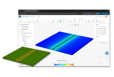
7) Product Update: New Post-Processor Releases
A first public version of SimScale’s new online post-processor has recently been released as an open beta to all SimScale users.
As promised, more and more features have been added meanwhile. Here a short summary of the current progress and what to expect next:
- [Released] Automatic rotating zones
When post-processing a simulation result that contains a rotating zone (transient/AMI), the rotating region will now be animated accordingly when playing a time step animation.
- [Released] Projecting vectors on cutting plane
The new post-processor now also allows for projecting vectors on a cutting plane. Find this option in the vector settings within the cutting plane controls.
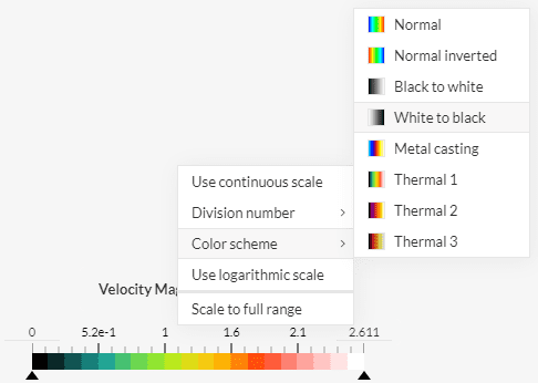
- [Coming soon] More color schemes
Requested by many users, the ability to change the color scheme applied to the model for a given result field will be released within the coming days. Find this option in the context menu of the legend bar controls.
- [Next] New post-processor for structural analyses
While currently only being available for fluid flow analyses, the new post-processing interface will soon also be available for all remaining structural analysis simulations.
How to Use This Product Update:
- When entering post-processing mode, you’ll be prompted with a choice to either continue using the old post-processor or try the new one.
- For now, the new post-processor is only available for Fluid Flow analysis types. The open beta phase for the remaining structural simulation analysis types will follow shortly.