Diodes, transistors, and integrated circuits generate considerable amounts of heat during operation. Extreme heat can damage or significantly affect the performance of semiconductor devices, and therefore, supplemental cooling is necessary to maintain the temperature within the limits specified by a manufacturer. Whereas some electronic components can dissipate heat on their own, most optoelectronic devices — like lasers and power transistors such as MOSFETs and IGBTs — cannot sufficiently dissipate heat without a heat management solution. How to dissipate heat in this case? This is where a well-thought-out heat sink design can make a big difference.
How To Dissipate Heat What are Heat Sinks Used For?
Heat sinks are used in electronic devices and assemblies to provide supplemental cooling that is required to prevent overheating of components. Using heat sink simulation software, engineers can test these designs virtually before prototyping. These elements are designed and optimized to ensure that electronic devices operate within the temperature ranges provided by manufacturers.
Despite the significant manufacturing cost reduction of electronic boards and enclosures for devices, it is still a daunting and time-consuming task to analyze the thermal performance of a new design. Download this case study to learn how to dissipate heat, and the thermal performance of a printed circuit board was investigated using thermal analysis in a web browser.

Heat sinks are designed using thermal conductive materials — like copper and aluminum — and they work by dissipating heat through liquid cooling, natural convection, forced convection, or radiation. Thermal management needs vary from one application to another. Therefore, it is essential to look beyond the heat sink when designing a thermal solution for a particular application. Some of the important factors that should be considered include heat sink level requirements, component level requirements, system-level requirements, and chassis-level requirements.
Heat Sink Design Key Considerations in Heat Sink Design
A heat sink transfers the thermal energy generated by an electronic assembly or component into a cooling medium. The heat is transferred from a higher temperature region (electronic component) to a lower temperature region (fluid medium) by conduction, convection, radiation, or by a combination of these heat transfer methods.
The performance of this passive heat exchanger is determined by many factors including the velocity of the coolant fluid, the thermal conductivity of the material, the thermal interface material, and the attachment method. For a specific application, the parameters of a heat sink can be precisely determined through modeling and analysis. To illustrate the key factors affecting the heat sink design performance, we used one of the public projects from the SimScale library — electronics cooling using conjugate heat transfer.
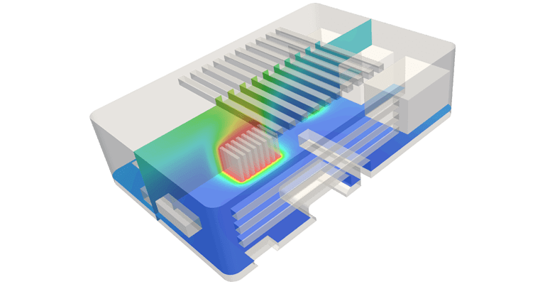
In this project, the heat flow in a heat sink design was simulated. To use it as a template, just create a free Community account here and then copy the project.
Download our ‘Electronics Cooling Guide’ now for a complete overview!

1. Thermal Resistance
Thermal resistance refers to the sum of resistances to heat flow between the die and the coolant fluid. These heat flow resistances include the resistance between the die and the component casing, the resistance between the casing and the heat sink (thermal interface resistance), and the resistance between the heat sink and the fluid in motion. Thermal resistance does not factor non-uniform heat distribution and it is unsuitable for modeling systems that are not in thermal equilibrium.
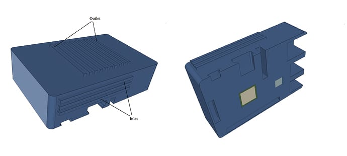
Although the thermal resistance value is an approximation, it enables the modeling and analysis of the thermal characteristics of semiconductor devices and heat sinks. Analyses of different heat sink designs are used to determine heat sink geometries and parameters that enable maximum heat dissipation. Complex modeling of thermal characteristics can be achieved by meshing heat sinks using 3D thermal resistances. The image below illustrates the mesh of an electronics enclosure design created in a web browser with the SimScale cloud-based simulation platform.
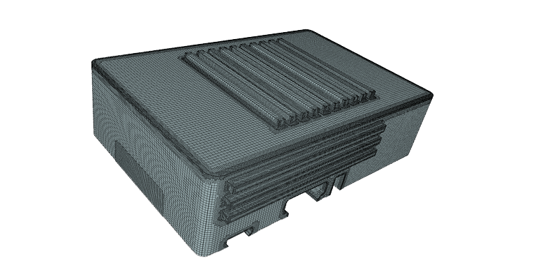
The hex-dominant parametric (only CFD) mesh was used to generate the mesh for the 4 volumes (3 solids and 1 fluid). This is used to create refinements and maintain the volumes as different regions to later define interfaces.
2. Material
Heat sinks are designed using materials that have high thermal conductivity such as aluminum alloys and copper. Copper offers excellent thermal conductivity, antimicrobial resistance, biofouling resistance, corrosion resistance, and heat absorption. Its properties make it an excellent material for heat sinks but it is more expensive and denser than aluminum.
Diamond offers a high thermal conductivity that makes it a suitable material for thermal applications. Its lattice vibrations account for its outstanding thermal conductivity. Composite materials such as AlSiC, Dymalloy, and copper-tungsten pseudo-alloy are also commonly used in thermal applications.
3. Arrangement, Shape, Size, and Location of Heat Sink Fins
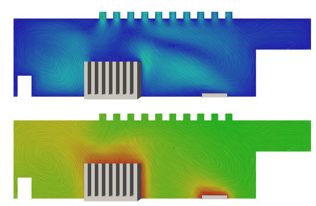
The flow of the coolant medium is greatly impacted by the arrangement of fins on a heat sink. Optimizing the configuration helps to reduce fluid flow resistance thus allowing more air to go through a heat sink. Its performance is also determined by the shape and design of its fins. Optimizing the shape and size of the fins helps to maximize the heat transfer density. Through modeling, the performance of different fin shapes and configurations can be evaluated.
4. Heat Sink Fins: Electronics Cooling Efficiency
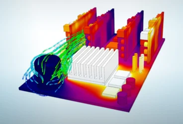
Heat sink fins receive heat from an electronic device and dissipate it into the surrounding coolant fluid. The heat transferred by a fin to the coolant medium decreases as the distance from the base of the heat sink increases. Using a material that has a higher thermal conductivity and decreasing the aspect ratio of the fins help to boost the fins’ overall efficiency. The following image is part of the results of a simulation investigating the temperature characteristics of a heat sink design.
5. How To Dissipate Heat: Thermal Interface Material
Surface defects, roughness, and gaps increase thermal contact resistance thereby reducing the effectiveness of a thermal solution. These defects increase the heat flow resistance by reducing the thermal contact area between an electronic component and its heat sink, and therefore the heat sink efficiency. Thermal resistance is reduced by increasing the interface pressure and decreasing the surface roughness. In most cases, there are limits to these resistance reduction methods. To overcome these limits, thermal interface materials are used. The electrical resistivity of a material, contact pressure, and size of the surface gaps should be considered when selecting a thermal interface material for a given thermal application.
6. How To Dissipate Heat: Heat Sink Attachment Methods
The thermal performance of a heat sink can be enhanced by selecting an appropriate method of attaching a heat sink to an electronic device or component. The selection process should factor in both the thermal and mechanical requirements of the thermal management solution. Common heat sink attachment methods include standoff spacers, flat spring clips, epoxy, and thermal tape.
Heat Sink Efficiency Design Conclusions
Heat sinks are essential parts of most electronic assemblies, power electronic devices, and optoelectronic components. These passive heat exchangers dissipate heat generated by electronic devices to ensure that they are operating within the limits specified by manufacturers. Some of the key factors that should be considered in heat sink design include thermal resistance, material, fin configuration, fin size and shape, fin efficiency, heat sink attachment method, and thermal interface material. Geometries and parameters that provide maximum heat dissipation are obtained by analyzing different heat sink models.
Download this free case study to learn how QRC Technologies used thermal simulation with the SimScale cloud-based CAE platform to optimize their design, improve heat sink efficiency, and prevent thermal damage to electronics. Alternatively, watch the recording of a webinar on “Thermal Simulation for Better Electronics Enclosure Design”. All you need to do is fill out this short form and it will play automatically.
If you’d like to read more about how to design a heat sink electronics cooling, this article might be of interest to you: Thermal Design for Electronics with Cloud-Based Engineering Simulation.