Electronics cooling refers to the thermal management of components within an electronic system. The rise of electronics in recent years and their continued miniaturization have led to a sharp increase in power density. As the trend for smaller electronics leads to more densely populated packaging combined with higher processing speeds, engineers are finding it more challenging than ever to develop suitable thermal management solutions.
Due to this, the adequate removal of heat flux, as well as uniform power dissipation, have become the main goals in thermal management. Temperature control is necessary to ensure that electronic devices perform at their optimal capacity and within design parameters. When a system’s components are at risk of overheating, reduced operational ability, or even catastrophic system failure is possible.
In tackling this design challenge, electronics cooling emerges as the vital process of cooling components within electronic systems to prevent overheating and ensure performance.

Why is Electronics Cooling Important?
In an absence of the right cooling strategy, the lifespan of components can decrease, and the respective electronic device will operate at an optimal level. Adversely, failure to effectively cool electronics and microprocessors can lead to loss of energy and even system malfunction or destruction.
Therefore, high-performance microchips and electronic devices of all shapes, sizes, and levels of functionality need innovative thermal design techniques. Furthermore, coolants with high heat transfer capability are also essential to improve the heat removal rate and thus maintain normal operating temperatures.
How Does Electronics Cooling Work?
When it comes to electronic systems, there are 4 main active and passive cooling mechanisms, shown here in order of cooling requirements.
Natural Convection Electronics Cooling: These applications are characterized by passive heat sinks made from copper or aluminum sheet. They rely on the air being driven by purely the heat rising and pulling through colder air below.
Forced Convection Electronics Cooling: These applications require artificially produced air velocity from a fan within the system to provide additional levels of cooling.
Fluid-Phase-Change Electronics Cooling: These applications are also known as ‘re-circulation cooling’, as closed loop heat pipes integrated into the system allow for an accelerated movement of heat transfer through the evaporation and condensation within their structure.
Liquid-cooled Electronics Cooling: These applications incorporate cold plates, a heat exchanger, and a pump system to circulate cold fluid past a heat source.
Why Use CFD for Electronics Cooling Applications?
In the past, electronics cooling was a tedious process riddled with frustrations that accompany trial and error or standard prototype testing.
Today, thermal simulation using fluid flow analysis (CFD) allows engineers to easily test their designs without wasting valuable time and resources. Online simulation is a fast and cost-effective method of evaluating and optimizing the heat transfer processes in a wide range of prototype geometries and working conditions.
Here at SimScale, our Public Projects Library is full of electronics cooling simulations for applications. This article will share five ready-to-use electronics cooling projects that will help you get started on your very own design, no matter what your skill level is!
1. Optimize Electronics Package Cooling With CFD: Electronics Cooling
This electronics package cooling project investigates the performance of the device’s ventilation capabilities in order to guarantee optimal operating conditions. The appropriate conditions are only met when the working temperature of the installed components lies within a safety temperature margin.
Therefore, analyzing the conjugate heat transfer (CHT) processes within the electronics package design is necessary. This project demonstrates how users can use an online simulation to perform a parametric study to optimize the rate of inlet airflow.
Electronics Cooling Simulation
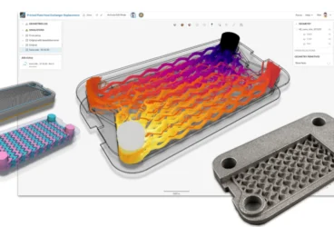
The electronics cooling simulation tests the air cooling performance of an electronic cabinet that includes forced convection. It uses a steady-state 3D viscous flow problem involving coupled heat transfer between the solid-fluid medium that is solved by the conjugate heat transfer (CHT) solver in SimScale.
The electronics enclosure measures overall dimensions W x L x H = 1.5m by 2m by 0.5m, and a hex-dominant parametric mesh was created within the platform. The CFD simulations presented utilized fully 3D CHT with forced external air convection and solid conduction. The results for temperature distribution, flow vectors, and streamlines from the simulations are illustrated within the project.
Results
The electronics cooling simulation results reveal how the fan inlet flow rate can be optimized to result in maximum temperature reduction within the electronics package. The project reinforces how important managing heat is in power electronics design. Using a combination of CHT and CFD analysis is an excellent way to evaluate your design before physical prototyping.
2. Thermal Analysis of CPU with Different Heat Sinks
This project explores how a central processing unit (CPU) within a personal computer can be best cooled while being effective and economical for the system. A CPU is an integrated circuit within a machine that carries out the instructions of a computer program by performing the basic arithmetic, logical, controlling, and input/output operations specified by the instructions. In order to discern the best cooling mechanism methodology for a CPU, the simulation presented focuses on trialing different heat sink designs.
Electronics Cooling Simulation
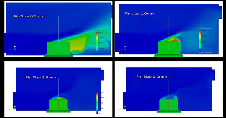
To thermally analyze the CPU with different heat sinks, a parametric study measuring different fin widths is executed. The simulation investigates the heat transfer between the solid sink and fluid as heat is generated inside the solid at 80W.
In this case, the fluid flow (air or liquid) is assumed to be incompressible as well as laminar, meaning the temperature fluctuation only changes the density of the fluid. The case is then solved until a viable temperature at the face of the chip had been reached, achieving a steady solution.
Download our ‘Electronics Cooling Guide’ now for a complete overview!

Results
The simulation ultimately finds that by assessing the thermal states at different fin widths, a thin fin is best for dissipating heat within the particular system. Once again, this project demonstrates how using CFD from SimScale can benefit the early stages of design and allow the most efficient solutions to come to fruition.
3. Water-Cooled Electronics: Electronics Cooling
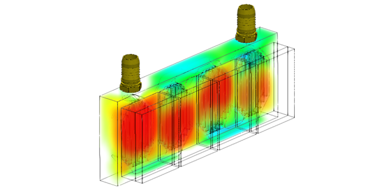
As we already know, electronics cooling is one of the main success factors of any electronic operation. Water cooling as a subset of component cooling is a popular option for higher power applications, and for good reason, as it can transfer more heat from a device than air without dramatically increasing its temperature. This project explores how water cooling can be used within a system containing multiple insulated gate bi-polar transistor (IGBT) modules.
Electronics Cooling Simulation
This simulation tests the cooling of multiple IGBTs, which are highly efficient fast-switching transistors, generally useful in high-load applications. The simulation conditions assume that each IGBT was dissipating 368W of energy with heat generation modelled as a volumetric heat source, and materials are given standard values for thermal conductivity and specific heat capacities.
Results
The simulation results reveal that the design allows for uneven cooling, large temperature gradients, and unacceptable temperatures in the component. For more information regarding water-cooled electronics, check out our webinar that delves further into this project.
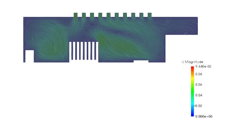
4. Conjugate Heat Transfer Analysis of a Heat Sink
This project gives an educational overview of the crucial role a heat sink can play in a design, as well as how to best analyze heat sink thermal performance using conjugate heat transfer analysis (CHT). Whether the medium fluid is air or liquid, a heat sink removes heat from the chip or PCB board, thereby regulating the temperature of the device. The typical applications of CHT include simulating heat exchangers, cooling electronic equipment, and general-purpose heating/cooling systems.
Electronics Cooling Simulation
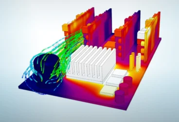
With the help of the SimScale platform, the heat flow from an aluminum heat sink is simulated to the surrounding cooling fluid (air) using the CHT method. The different geometric solid volumes tested are the heat source, heat sink, and fluid region. A multi-region, hex-dominant parametric mesh is mapped onto the geometry with 16 computing cores, and a mesh refinement is made on the entire surface area of the heat sink.
After the setup is completed, a steady-state simulation with a turbulence model of laminar flow is executed. The boundary conditions are selected, and with 32 computing cores, the simulation is run and takes a total of approximately 150 minutes.
Results
The results from the electronics cooling simulation give us a quick overview of the application. It helps us in understanding the characteristics of two main phenomenons happening in the system:
1) The efficiency of the heat sink in taking away the heat from the chip (heat source).
2) How forced convection aids in removing the dissipated heat, thereby cooling down the system effectively.
For more about thermal simulation with SimScale, check out our Public Projects Library.
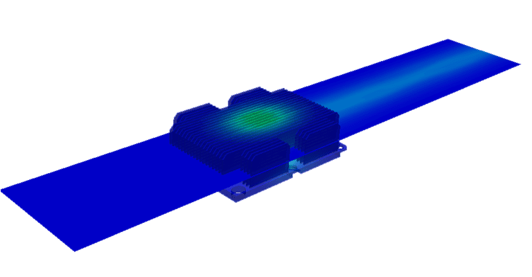
5. Electronics Cooling Simulation with the CHT Method & ParaView
This project features an electronics cooling simulation using the conjugate heat transfer (CHT) method and demonstrates an electronic cooling application of ICs on a PCB. As mentioned before, CHT defines processes which involve variations of temperature within solids and fluids due to thermal interaction; namely between a heat sink and a fluid.
For the choice of heat sink material, it would be best to employ a material that has a high thermal conductivity. A finite element simulation with numerical results would give us a better idea of the performance of different designs and materials. The simulation results include how to best pair SimScale results with ParaView for post-processing visualization.
Electronics Cooling Simulation
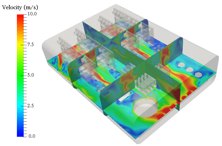
The simulation setup includes air flow at room temperature, two heated electronic chips and a heat sink at an intermediate temperature. A laminar, steady-state simulation is carried out using CHT. This analysis type eliminates the need for the heat transfer coefficient. Check out the project on SimScale’s workbench for more detailed information.
Results
The electronics cooling simulation results show how you can gather your post-processing results (temperature contours, temperature, and velocity) and locally upload, adjust, and render them in ParaView, as illustrated by the above image.
Electronics Cooling Conclusion
To learn more about automatic or hex-dominant parametric meshing, CHT for electronics cooling, and much more, look no further! Here at SimScale, we have the largest collection of CFD, FEA, and thermal simulation projects publicly accessible to help you get started on your electronics cooling design today.