HVAC design gets expensive fast.
A suboptimal duct bend. An undersized diffuser. A mixed-mode strategy that fails thermal comfort at occupancy. Each one means physical prototypes, field tests, and redesigns late in the process, when changes cost the most.
CFD ventilation simulation cuts that loop short.
This guide covers two scales of analysis:
- Component level: AHUs, diffusers, louvres, fans: pressure drop, discharge coefficients, flow optimization
- Spatial level: building IAQ, CO2 distribution, thermal comfort validated against ASHRAE 55, CIBSE, and LEED standards
Launch your own ventilation simulation today!
Real case studies. Quantified results. Workflows engineers run in SimScale today, from a browser, no HPC required.

What Is CFD Ventilation Simulation?
CFD ventilation simulation predicts airflow rates, pressure drop, temperature distribution, CO2 concentration, and thermal comfort across HVAC components and occupied spaces, without physical prototyping. It operates at two scales: component level (AHUs, diffusers, louvres, fans) and spatial level (room air quality, occupant comfort, mixed-mode strategies).
The Core HVAC Design Problem
Two factors drive almost every ventilation design challenge:
Pressure drop: each component resists airflow. The losses compound through dampers, grilles, filters, and duct bends. Two mechanisms dominate:
- Friction: air rubbing against duct surfaces loses energy. Duct length, surface roughness, and filter loading all contribute.
- Turbulence: direction changes, particularly 90° bends, produce secondary vortices. Fitting geometry at each bend determines how severe the loss is.
System-level compensation: when one component underperforms its pressure-flow target, adjacent equipment compensates, driving up energy consumption and accelerating wear across the whole system.
CFD exposes exactly where losses originate and lets engineers test fixes in parallel, before any hardware is committed.
Ventilation Simulation for HVAC Components
Air Handling Units (AHUs)
CFD covers three areas of AHU performance analysis:
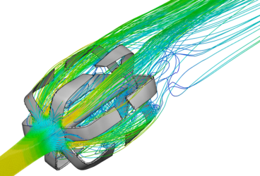
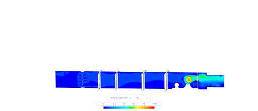
Flow simulation: modeling air through each component in sequence (dampers, filters, heating coils, mixing chamber, supply fan) reveals true installed performance. Parallel simulations are the fastest way to evaluate component substitutions or assess the effect of varying operating temperatures.
Pressure drop analysis: CFD calculates drop through each component and across the full system at specified flow rates and temperatures. Angle-dependent losses through dampers are reduced by optimizing fin angles or introducing guide vanes to suppress flow separation. Filters are modeled as porous media; their drop is computed directly from permeability coefficients.
Structural and aero-acoustic analysis: pressure loads from blowers and fans map onto structural analysis to identify stress concentrations and noise sources, both of which must be minimized for compliance.
Ventilation Louvres and Grilles
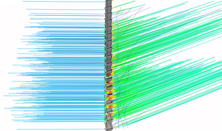
For louvres, CFD determines:
- Discharge coefficient (Cd): efficiency and compliance with design standards
- Aerodynamic behavior: stagnation points, high-velocity zones, flow separation, and wake propagation that identify where pressure loss originates
- Porosity factors: Darcy and Forchheimer coefficients through porous modeling, used to build pressure loss curves for comparative sizing
Case study: Smartlouvre MicroLouvre™
Smartlouvre Technology Ltd used SimScale to characterize their MicroLouvre™ metal fabric, an external window attachment that provides natural ventilation and solar shading. A digital wind tunnel at multiple wind speeds and incidence angles produced a discharge coefficient of Cd = 0.39. That value feeds directly into building simulation and thermal modeling tools used by architects integrating MicroLouvre into their designs, eliminating the need for physical wind tunnel testing.
HVAC Diffusers
Diffuser geometry, grille orientation, and placement directly determine room air distribution. Building authorities increasingly require quantitative evidence of mixing performance, not handbook estimates.
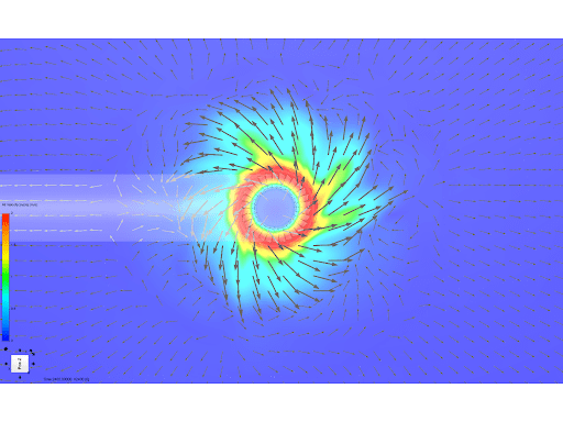
Swirl diffuser: a radial swirl diffuser simulated in SimScale demonstrates the Coanda effect: flow vectors follow the outlet curvature to produce the characteristic outward swirl that improves mixing. Velocity vectors are shown in both plan and section.
Case study: Monodraught HVR Zero
Monodraught used SimScale to develop the HVR Zero, a compact hybrid ventilation and cooling unit. Parallel simulation across multiple internal air path geometries identified and eliminated recirculation zones, reducing fan power consumption by 50%. That reduction compounds across every building deployment.
Building Ventilation and Indoor Air Quality
At the spatial level, CFD answers the questions energy models cannot: where does fresh air actually reach occupants? Where does CO2 accumulate? Where does thermal comfort fall short? SimScale imports geometry directly from Rhino®, Revit®, SketchUp, and AutoCAD®, enabling parametric multi-configuration studies without geometry rebuilds.
Analysis Type: Conjugate Heat Transfer (CHT)
CHT is the correct analysis type for building-scale ventilation. It resolves simultaneously:
- Natural convection: buoyancy-driven and wind-driven airflow
- Forced convection: mechanical supply and extract
- Radiation: solar gains and radiant surfaces
- Passive scalar transport: CO2, aerosols, and VOCs via diffusion coefficient
This covers passive, mechanical, and mixed-mode systems in a single simulation run.
Case Study: Mixed-Mode Ventilation in a Classroom
A parametric classroom model tests three configurations (occupant thermal loads from ASHRAE/LEED/CIBSE guidelines, LED lighting, laptops, display screen, 0.1 ACH adventitious leakage at 15°C ambient):
- Base case: horizontal diffusers only (supply downward)
- Configuration 1: upward-directed diffuser grilles
- Configuration 2: upward diffusers + top-hung windows open (mixed-mode)
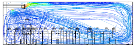
The base case creates downdraught at desk level: cold supply air drops due to density difference, leaving upper zones under-ventilated. Configurations 1 and 2 redirect supply upward; Configuration 2 adds cross ventilation from the open windows.

Base Configuration – Diffuser grills are set horizontally at the inlet – Cold air from the supply tends to move downward due to the ambient condition
Configuration 1 & 2 – Upward facing grills creates a better circulation of fresh air inside the room
CO2 and Indoor Air Quality
The passive scalar model tracks CO2 from each occupant’s head position, producing spatial concentration maps that single-point energy models cannot generate.
| CO2 Concentration | Assessment |
|---|---|
| < 800 ppm | Excellent |
| 800–1,000 ppm | Good; acceptable for controlled ventilation spaces |
| 1,000–1,500 ppm | Marginal; permitted for purely naturally ventilated buildings under some codes |
| > 1,500 ppm | Poor; impairs cognitive function |
| > 2,000 ppm | Very poor; significant health risk |
Configuration 2 delivers 22% less CO2 than Configuration 1. Open windows introduce outdoor air at ~400 ppm and drive cross ventilation. The simulation pinpoints stagnant zones, directly informing sensor placement and exhaust positioning.
The same passive scalar approach extends to aerosol tracking, VOC off-gassing, and cleanroom contamination control.

Base Configuration – High concentrations of CO2 at the ceiling level due to improper mixing of fresh air
Configuration 1 & 2 – Better mixing of air, drastically reduces the concentration levels
Thermal Comfort Standards
PMV and PPD outputs are evaluated against ASHRAE 55 and ISO 7730:
| Standard | PMV Range | PPD Limit |
|---|---|---|
| ASHRAE 55 | −0.5 to +0.5 | < 10% |
| ISO 7730 (new buildings) | −0.5 to +0.5 | < 10% |
| ISO 7730 (existing buildings) | −0.7 to +0.7 | < 15% |
The classroom configurations sit within −0.6 to +0.6 PMV. The primary differentiator between configurations is air quality and mixing, not temperature. PMV can be improved further by adjusting supply inlet temperature, fabric thermal performance, or adding heat recovery on extract air.

“The SimScale platform has allowed us to develop and test scenarios including ventilation flow paths and understanding the dynamics between building fabric, airtightness, window natural ventilation design, and CO2 concentrations in various utilization scenarios. The platform has given us quality, visually digestible output to inform decision-making and to compare results against our monitored data from our extensive post-occupancy studies. Working with SimScale has allowed us to study our learning spaces in a way we never have before.”
Robert White
Technical Associate and CEPH Designer at Architype
Natural Ventilation Simulation
For passive and mixed-mode strategies, SimScale supports external wind CFD for facade pressure coefficients and cross-ventilation potential, alongside CHT for stack-effect and buoyancy-driven analysis. See the natural ventilation validation guide for a full methodology walkthrough.
Ventilation Simulation Software That Runs in Your Browser
SimScale is the world’s first AI-native cloud platform for engineering simulation, trusted by 800,000+ engineers. For HVAC and ventilation work, that means:
- Engineering AI automates simulation setup (mesh generation, boundary condition assignment, solver configuration) so engineers spend time on design decisions, not manual workflow
- Physics AI delivers instant predictions connected to high-fidelity CFD, enabling design space exploration across thousands of variants before committing to a full solve
- No HPC, no VPN, no installation: runs in a standard browser with elastic cloud compute on demand
- All physics, one platform: incompressible and compressible CFD, CHT, passive scalar, structural, and radiation in a single environment; no solver switching
- CAD-native imports: Rhino®, Revit®, SketchUp, AutoCAD® and more; geometry changes propagate directly into simulation
- Standards-aligned outputs: PMV, PPD, age of air, CO2 in ppm, discharge coefficients, and pressure drop curves for every major HVAC design standard
Frequently Asked Questions
CFD ventilation simulation models airflow, pressure drop, temperature distribution, and contaminant concentration across HVAC systems and building spaces, predicting performance without physical prototypes.
HVAC simulation targets component design (AHUs, diffusers, louvres, fans, ductwork), optimizing pressure-flow characteristics. Building ventilation simulation analyzes how that equipment performs spatially: where air distributes, where CO2 accumulates, whether thermal comfort standards are met across the occupied volume. SimScale handles both scales in one environment.
Conjugate Heat Transfer (CHT) for building-scale work: resolves natural and forced convection together with buoyancy effects and passive scalar transport for CO2 and contaminants. Incompressible CFD for isothermal component studies (pressure drop, discharge coefficient).
CO2 is a passive scalar species with a defined diffusion coefficient. Sources are applied at occupant positions; the solver computes spatial concentration throughout the space, revealing exactly where stale air accumulates and where ventilation equipment fails to reach.
The gas turbine case study above achieved 16% pressure drop reduction (over 80 Pa) by replacing sharp bends with guide vanes and rounded corners. For a 160 MW turbine, a 250 Pa reduction is worth ~$480,000/year in recovered output. The same principles apply to AHUs, duct networks, and building systems.
Component-level studies: 1–3 hours. Room-scale building simulations: 2–6 hours. Multiple variants run in parallel, so a 10-configuration parametric study takes roughly the same wall-clock time as a single run.
Yes: external wind CFD for facade pressure coefficients and cross-ventilation potential; CHT for stack-effect and mixed-mode analysis. See the natural ventilation validation guide.