Ever wondered how engineers figure out whether a new car design will slice through the air efficiently, or whether an electronics enclosure will overheat under load? They don’t always build a physical prototype and test it in a wind tunnel or test bench. Instead, they turn to Computational Fluid Dynamics, or CFD.
CFD analysis uses computer simulations to predict how fluids (liquids and gases) behave when they flow around or through objects. Think of it as a virtual wind tunnel, thermal chamber, and flow lab rolled into one. Instead of months of physical testing, engineers can explore dozens of design variations in hours or days, catching problems early and optimizing performance before anything gets built.
Launch your own CFD analysis
With SimScale you can do CFD analysis on any item of your choosing from cows to space shuttles – no limits!
If you’re looking for a deep dive into the theory behind CFD, our What is CFD guide in SimWiki covers the fundamentals in detail. This article focuses on the practical side: how CFD analysis actually works, where it’s used, and how to get started.
Key Aspects of CFD Analysis
At its core, every CFD analysis sits at the intersection of three things:
Physics: the laws governing how fluids move and transfer heat. These are well-established (we’ve known the governing equations since the 1800s), but solving them for real-world geometries is incredibly complex.
Numerics: the mathematical techniques that break those impossible-to-solve-by-hand equations into millions of smaller, approximated – and crucially, solvable pieces. This is what makes CFD possible: turning continuous physics into discrete calculations a computer can crunch through.
Computing: the hardware and platforms that do the actual number-crunching. This used to mean expensive on-premises HPC clusters, but cloud-native platforms have changed the game entirely. Today, an engineer with a browser can access more simulation horsepower than a NASA lab had in the 1990s.
What’s exciting about where CFD is today is that all three of these pillars have matured to the point where CFD is no longer reserved for aerospace specialists. Engineers across automotive, HVAC, electronics, energy, and dozens of other fields use it daily to make better design decisions, faster.
Core Principles
The Navier-Stokes Equations
You don’t need to solve these by hand (that’s what the software is for), but it helps to know what’s under the hood. The Navier-Stokes equations are the mathematical backbone of CFD. They describe how velocity, pressure, temperature, and density in a fluid are all related – essentially encoding Newton’s second law for fluid motion, plus conservation of mass and energy.
For most everyday engineering problems (water in pipes, air around buildings, coolant in electronics), we use the incompressible form of these equations. When things get fast (think supersonic aircraft or gas dynamics) or hot (like a plume of hot air inside a data center), constant density can no longer be assumed and the compressible form kicks in.
Heat Transfer
Many CFD problems aren’t just about flow. They’re about thermal performance too. A simulation might need to account for several heat transfer mechanisms working simultaneously:
- Conduction: heat spreading through solid materials, like a heatsink drawing warmth away from a chip
- Convection: heat carried by moving fluid, like a fan blowing cool air across a circuit board
- Radiation: electromagnetic heat transfer, which matters at high temperatures (think furnaces or LED lighting)
The beauty of modern CFD is that it handles all of these together in a single simulation, giving you a complete picture of what’s actually happening thermally in your design.
How to Perform a CFD Analysis
So how does a CFD analysis actually work in practice? Whether you’re simulating airflow over a vehicle or heat dissipation in an electronics enclosure, the workflow follows a consistent pattern. Here’s the process, broken into the stages you’ll go through on every project.
1. Define the Problem
Before you touch any software, get crystal clear on what you’re trying to answer. “Reduce pressure drop across our valve by 15% while maintaining flow rate” is a great problem statement. “Make the valve better” is not.
This step sets the direction for everything that follows. The geometry you’ll need, the physics you’ll model, the results you’ll extract. Skip it, and you’ll waste hours simulating things that don’t matter.
2. Prepare the Geometry
Import or create your 3D model, then define the fluid domain (the space where the fluid actually flows). This is also where you simplify: strip away small features like bolt holes or fillets that won’t affect the flow but will add unnecessary complexity to your mesh.
The art here is knowing what to keep and what to remove. For an external aerodynamics study, you need the vehicle body and surrounding air volume, but you can simplify the underhood geometry and hidden components like brake calipers. For a pipe flow analysis, the internal (wetted) surfaces matter; external details generally don’t.
3. Choose Your Simulation Strategy
This is where you make the key modeling decisions. Is the flow steady-state (unchanging over time) or transient (evolving)? Is the boundary layer flow laminar (low Reynolds number) or turbulent (after transition)? Incompressible (most liquid flows) or compressible (high-speed gas flows or natural convection driven)? Single-phase or multiphase (like fuel sloshing in a tank)?
Each choice is a tradeoff between accuracy and computation time. A transient, multiphase simulation captures more physics but takes dramatically longer than a steady-state, single-phase run. Match your approach to the question you’re trying to answer. Not every problem needs the most expensive model.
4. Configure Material Properties and Solver Settings
Set the physical properties of your fluid (density, viscosity, thermal conductivity) and dial in the solver settings: numerical schemes, convergence criteria, time step size for transient runs. These details might seem minor, but they determine whether your simulation converges smoothly or crashes halfway through.
5. Set Boundary and Initial Conditions
This is where you tell the solver what’s happening at the edges of your domain. Where does flow enter (and at what speed)? Where does it exit? Which surfaces are walls? Are any surfaces externally heated or cooled?
Getting these right is absolutely critical. Boundary conditions are the inputs to your simulation. If you put garbage in, you’ll also get garbage out. Common boundary condition types are inlet velocity, outlet pressure, no-slip walls, and symmetry planes (which let you simulate half the geometry and save computation time).
6. Generate the Mesh
The flow solver works on a discretized representation of your simulation domain. This is where meshing comes in – an automatic algorithm that divides your fluid domain into thousands, often millions, of tiny cells. The solver will calculate flow properties at each cell, so the mesh essentially determines the resolution of your simulation, in the same way that the number of pixels determines the resolution of an image.
Finer meshes capture more detail but take longer to solve. Coarser meshes are faster but may miss important flow features. The sweet spot? Refine the mesh where it matters most (near walls, around sharp edges, in regions with velocity and pressure gradients) and keep it coarser in calmer, more uniform areas. Boundary layer meshes near walls are especially important for correctly predicting viscous drag or heat transfer.
7. Run the Simulation and Monitor Progress
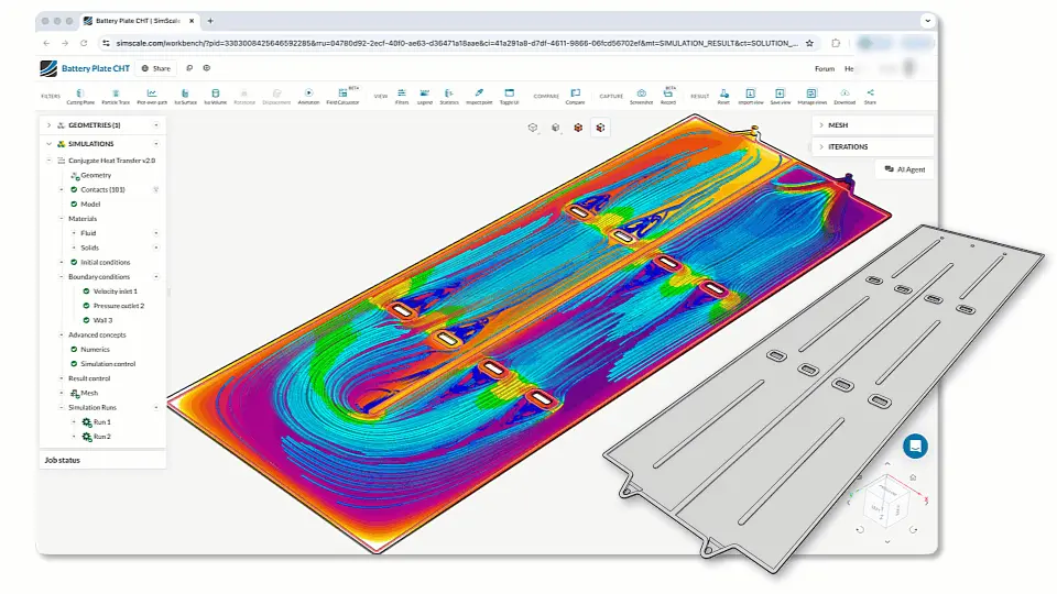
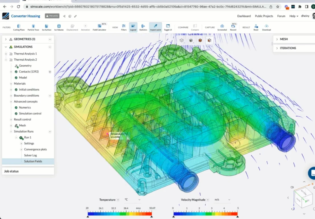
Hit run and watch the solver iterate toward a solution. On cloud-native platforms like SimScale, this means your simulation runs on remote servers, no need to tie up your local machine. Keep an eye on convergence plots and residuals in real time. If something looks off (residuals climbing instead of dropping, non-physical oscillations), it’s better to stop early and diagnose than to wait for a bad result.
8. Post-Process and Extract Results
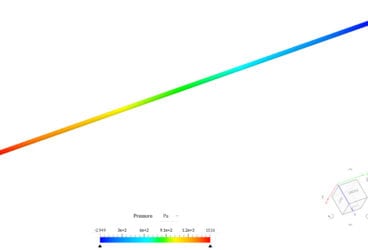
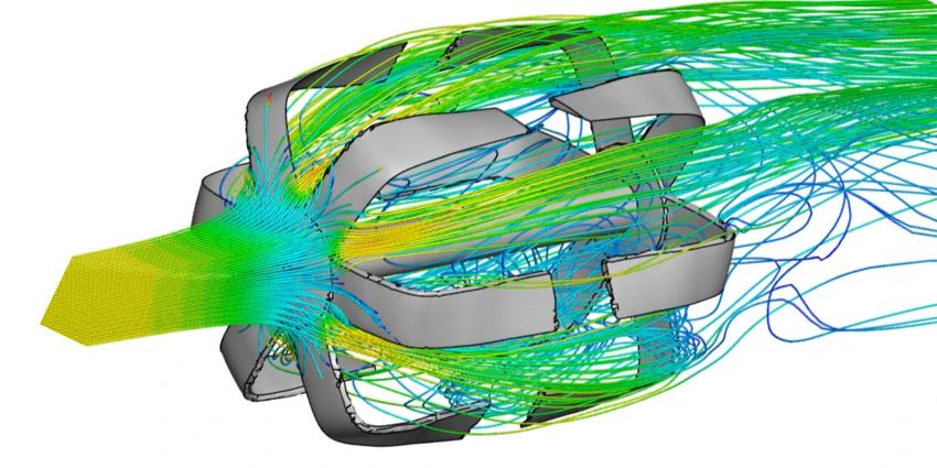
This is where simulation becomes engineering insight. Visualize velocity fields, pressure contours, temperature distributions, and streamlines. Extract the specific numbers you care about: drag coefficient, pressure drop, maximum surface temperature, heat flux.
Good post-processing isn’t just about pretty pictures. It’s about answering the question you defined in Step 1. Did the pressure drop decrease? Is the thermal hotspot within spec? Where is the flow separating?
9. Validate Against Real-World Data
A simulation is only as trustworthy as its validation. Compare your CFD results against experimental data, analytical solutions, or published benchmarks whenever possible. Run a mesh independence study (progressively refine the mesh to confirm results aren’t changing with resolution).
This step is what separates a “cool visualization” from an engineering tool you can make decisions with. SimScale’s pedestrian wind comfort analysis, for example, has been validated against wind tunnel experiments by the Architectural Institute of Japan (AIJ).
10. Iterate, Optimize, and Document
With a validated model in hand, now you can explore. Change the geometry, tweak parameters, run design variations. Cloud-native platforms make this fast: you can run multiple simulations in parallel rather than waiting in a queue.
Once you’ve found the optimal design, document everything: methodology, assumptions, results, lessons learned. This isn’t just good practice: it’s essential for design handoff, regulatory compliance, and making sure your team doesn’t repeat work six months from now.
Key Applications of CFD Analysis
One of the things that makes CFD so powerful is its versatility, the same underlying physics engine that predicts drag on a race car can also model airflow in a hospital ward or coolant flow in a battery pack. Here’s a snapshot of where CFD is making a real impact:
| Industry | Primary CFD Applications | Example Outcomes |
|---|---|---|
| Automotive | Aerodynamic drag reduction, airflow in cabins, underhood cooling, powertrain thermal management | F1 downforce optimization; 5-10% fuel efficiency gains; improved thermal comfort in EVs |
| Aerospace & Aviation | Wing aerodynamics, engine inlet design, cabin pressure distribution, icing analysis | Aircraft fuel efficiency; drag reduction; flutter prevention |
| Manufacturing | Heat exchangers, convection ovens, mixer design, spray optimization | Increased overall effectiveness; reduced device failure rates; optimized production throughput |
| HVAC & Building Design | Thermal comfort analysis, pedestrian wind comfort, ventilation effectiveness, wind microclimate | Energy-saving building designs; optimized HVAC ductwork; improved indoor air quality |
| Electronics & Thermal Management | Chip cooling, enclosure thermal analysis, airflow in data centers | Reduced thermal hotspots; extended component lifespan; lower cooling costs |
| Energy & Renewables | Wind turbine aerodynamics, hydrofoil design, geothermal flow paths, solar thermal systems | Optimized blade designs; increased energy capture; improved system efficiency |
| Marine & Offshore | Hull hydrodynamics, propeller design, subsea pipeline flows, wave loading | Reduced drag; improved fuel consumption; enhanced seakeeping performance |
| Oil & Gas | Multiphase flow in pipelines, separator design, subsea cool-down analysis | Increased shut-in window; multiphase flow assurance; failure prevention |
Benefits of CFD Analysis
Why has CFD become such a fundamental part of modern engineering? It comes down to a few things:
It compresses your development timeline. Product cycles keep getting shorter, and companies that can iterate faster win. CFD lets you test 20 or more design variations in the time it would take to build and test one physical prototype. Simulation fundamentally changes how quickly you can innovate.
It lets to discover more innovative solutions. Often the most important design decisions that determine how well a product performs are made during the concept design stage – before detailed CAD drawings and physical prototypes are developed. By leveraging simulation early on (the ‘shift left’ idea), design teams can quickly prove or disprove these concepts, de-risking the selection.
It catches problems before they become expensive. Discovering a thermal hotspot or a pressure drop issue in simulation costs you a few hours of compute time. Discovering it after you’ve tooled up for manufacturing costs you months and potentially millions. CFD pushes failure detection earlier in the design process, where changes are cheap.
It reveals physics you can’t see any other way. You can’t stick a thermometer inside a running jet engine, but you can visualize the complete temperature field in a CFD simulation. You can’t see how airflow separates around a building corner, but CFD shows you exactly where pedestrians will face uncomfortable wind speeds. This visibility drives better engineering decisions.
Not long ago, CFD required specialized workstations, dedicated analysts, and expensive software licenses. Cloud-native platforms have changed that equation. Today, production-quality simulations are accessible to entire engineering teams. Physics AI and Engineering AI are pushing this further, automating setup tasks and delivering instant predictions so teams can explore thousands of engineering decisions in seconds.
CFD Analysis Techniques
Not all CFD simulations are created equal. Depending on your problem, you’ll reach for different tools in the CFD toolkit. Here’s a quick orientation:
Turbulence Modeling
Most real-world flows are turbulent (think of smoke rising from a candle: smooth at first, then chaotic). How you model that turbulence has a huge impact on accuracy and cost:
- Laminar solvers work for slow, orderly flows (microfluidics, some pipe flows at low speeds)
- RANS models (k-ε, k-ω SST) are the workhorses of industrial CFD. They average out turbulent fluctuations and give you good results at reasonable cost
- LES (Large Eddy Simulation) and DES (Detached Eddy Simulation) are high-fidelity methods that resolve the larger turbulent structures and model the smaller ones, giving better accuracy for flows with complex separation or mixing
- DNS (Direct Numerical Simulation) resolves everything. Incredibly accurate, but computationally expensive enough that it’s mostly used in research
For most industrial engineering applications, RANS and DES (hybrid RANS-LES) models hit the right balance of accuracy and speed.
Steady-State vs. Transient
If your flow doesn’t change over time (airflow around a car moving at constant speed), a steady-state simulation is faster and simpler. If things are evolving (e.g. moving geometry or boundary conditions changing) you’ll need a transient simulation that marches through time step by step.
Beyond Standard Flows
Modern platforms handle much more than simple air-over-a-box scenarios. You might need compressible solvers for high-speed aerodynamics, multiphase modeling for air-water interfaces, porous media for flow through filters or heat exchangers, non-Newtonian models for polymer or blood flow, or conjugate heat transfer to capture both fluid flow and solid conduction in one simulation.
SimScale’s cloud-native simulation platform integrates all of these capabilities in a single environment, so you can match your approach to your problem without juggling multiple tools.
How CFD Compares to Real-World Testing
A fair question: can you actually trust CFD results? The short answer is yes! When the simulation is set up correctly and validated properly. Here’s what that looks like in practice:

“We have been using SimScale to modify and develop new solenoid valves. SimScale is one of our reliable computational tools to solve our fluid problems to make sure our solenoid-valves fluid performance is reliable.”
Simulation Manager at Solero Technologies
Solero, an automotive Tier 1 supplier, used CFD to validate solenoid valve designs and optimize fluid performance. The results were reliable enough to pursue 10 new business opportunities; all based on simulation-driven decisions.

By using cloud-native CFD in SimScale, the project resulted in savings of 45% compared to using traditional desktop software. This flexibility and cost-saving were the convincing factors for entering into a partnership with SimScale, considering the large scale of customers we serve daily on a global scale.
AI Engineer at RLE International Group
RLE, a 2,300+ employee engineering services firm, integrated cloud-native CFD with AI into their automotive aerodynamics workflows. Going from hours of analysis time to seconds!
The key to building this kind of trust is rigorous validation: benchmarking against experimental data, comparing to analytical solutions where they exist, running mesh independence studies, and following industry standards (ASME, IEEE, ISO). SimScale’s pedestrian wind comfort analysis, for example, has been validated against wind tunnel experiments by the Architectural Institute of Japan – demonstrating that cloud-native CFD can match laboratory precision.
CFD doesn’t replace physical testing entirely. The best practice is to use simulation to explore the design space broadly, then validate your final design experimentally. But it dramatically reduces how many physical tests you need, saving both time and money.
Getting Started with CFD Analysis
Ready to put this into practice? Here’s how to take the next step:
Explore the fundamentals. Our complete CFD guide digs deeper into the theory, and our CFD workflow quick guide walks through a practical project setup.
Try it hands-on. Browse our tutorials for guided walkthroughs covering automotive aerodynamics, thermal management, HVAC, and more. They’re designed to get you from zero to a working simulation in under an hour.
Start simulating for free. Create a free SimScale account and run your first simulation today. With 800,000+ users and a cloud-native platform that runs in your browser, there’s nothing to install and no hardware to worry about.
Talk to an expert. If you have a specific engineering challenge in mind, request a demo and our team will show you exactly how CFD can help.
Frequently Asked Questions
They’re complementary tools. CFD predicts how fluids behave: flow patterns, pressure distributions, temperatures in liquids and gases. FEA (Finite Element Analysis) predicts how solids behave: stress, strain, deformation. In practice, many engineering problems need both: you might use CFD to figure out the heat load on a component, then use FEA to check whether the resulting thermal expansion causes structural issues.
It depends on the complexity. A simple steady-state flow around a basic geometry might converge in 15–30 minutes. A detailed transient simulation with millions of mesh cells and complex physics could take several hours or even a couple of days. Cloud-native platforms help a lot here: they can parallelize across multiple servers, turning what might be a week-long run on a desktop into a few hours in the cloud.
Definitely not. Modern platforms like SimScale are designed to be accessible. Guided workflows, pre-configured templates, and AI-assisted setup mean you can get meaningful results without being a numerics specialist. That said, understanding the basics (what boundary conditions mean, why mesh quality matters, how to interpret results critically) will make you a much more effective user.
Three things: validation, mesh independence, and sanity checks. Compare your results to experimental data or published benchmarks. Refine your mesh to confirm the results don’t change significantly. And always ask yourself: does this result make physical sense? If your simulation shows air flowing backwards through an inlet, something is wrong – regardless of how converged the residuals look.
Not entirely, and that’s okay. CFD is unbeatable for design exploration: testing dozens of variations quickly and cheaply. Physical testing remains important for final validation, regulatory compliance, and catching unexpected phenomena. The smartest approach is to use CFD to narrow your design space from 50 options to 3, then physically test those 3. You get the best of both worlds.