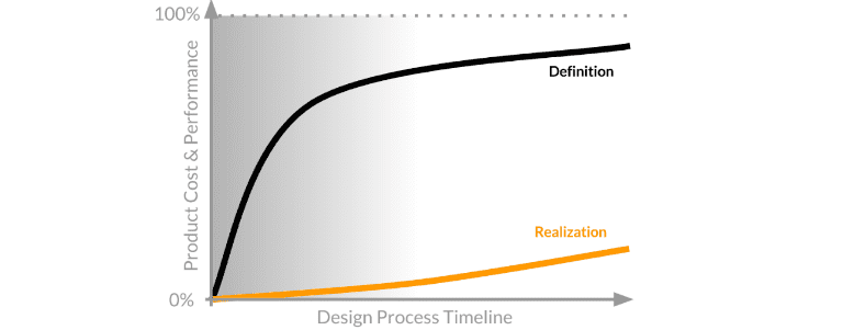
The cost and performance of any physical product are generally determined quite early on in the design process—the same holds true for ventilation system design. The stage when you begin to explore the design space and define your product concept is when the most impactful design decisions are made. After that, the rate at which the production costs are realized is much slower.
After all, it is much cheaper to have a design engineer work on a computer than it is to perform field testing, prototyping, and iterating. Simulation is one of the tools that play a fundamental role in those early product development stages, allowing engineers to make more informed design decisions earlier in the process, and reducing overall costs. For the final product, this can mean lower production costs, more efficient energy consumption, lower failure risk, and more.
Ventilation System Design Why SimScale?
Until recently, CFD (computational fluid dynamics) simulation tools have been inaccessible for many designers—despite their benefits. This is due to the high software and hardware costs, as well as the complexity of the multiphysics involved. This status quo has been challenged with the emergence of cloud-based CFD tools, which are rapidly turning CFD into an industry standard for HVAC (heating, ventilation and air conditioning). Today, performing the necessary simulation and analyzing the relevant design parameters is no longer the costly and time-consuming task it once was—the models are now fully and instantly accessible via a web browser without a large initial financial commitment, and cloud-based platforms like SimScale and Onshape have democratized computer-aided design and simulation. Freely available training content, as well as an intuitive user interface, have helped narrow the expertise gap and have allowed engineers who have limited prior experience with simulation software to quickly integrate it into their workflow and start extracting real value from it right away.
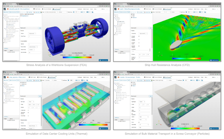
In addition to fluid dynamics (simulation of incompressible/compressible flow, laminar/turbulent flow, multiphase flow, etc.), which will be the focus of this article, the general purpose simulation environment of SimScale includes modules such as solid mechanics (static, dynamic, modal analysis, multibody dynamics, contact constraints etc), thermodynamics (conduction, convection, radiation, etc.), and more—with every customer getting access to the full range of physics simulation functionality.
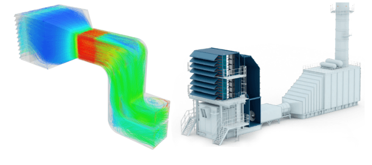
To illustrate the benefits of integrating simulation into your product design process, let’s consider a real-life engineering problem of optimizing ventilation system design, specifically the air intake system.
Ventilation System Design The Engineering Problem
Air intake systems play a vital role in air quality improvement for various engineering components, such as gas turbines and compressors, diesel engines, and more. A well-thought-out ventilation system design provides cool, clean air for combustion with even and minimized pressure drop. This improves the combustion efficiency and also reduces air pollution. To optimize the ventilation system design, it is essential to understand the flow and pressure drop throughout the system.
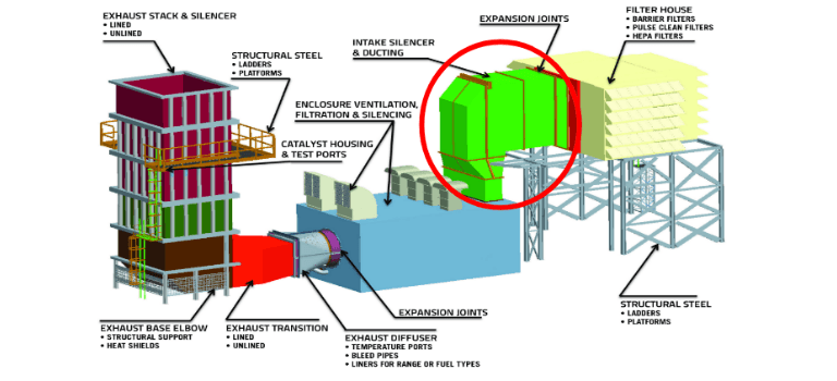
An air intake system (the green section pictured above) is an important part of a power plant gas turbine since a high drop in pressure leads to a drop in turbine’s gross power output. Optimizing the ventilation system design is an increasingly challenging process as both the layout complexity and the range of features that can be included in the intake system expands. These include a combination of insect or trash screens, whether there are protection and filtration systems, silencers, anti-icing systems, ventilation system offtakes, and inlet heating or cooling systems. Design flaws can result in an inefficient use of these components, as well as lower engine performance due to excessive pressure losses or distortion in the flow entering the gas turbine. High flow distortion, velocity, pressure or temperature, can induce compressor surge and high acro-mechanical stresses in compressor blades and vanes. In extreme cases, this may also result in blade or vane failures.
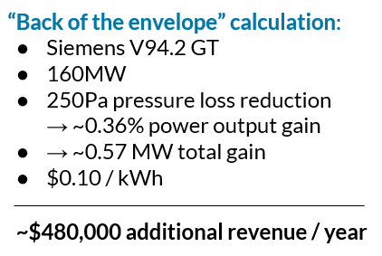 To get a quantitative estimation of how much such optimization can influence the system’s performance, consider the following example. A paper by Khashayar Khorsand et al. estimated that a pressure loss reduction of 250Pa in a Siemens V94.2 GT turbine with an output power of 160MW, is equal to 0.355% power output gain (or 0.568MW). At first glance, that may not seem like a lot. But consider the long-term implications—over a 12-month period of use at $0.10/kWh, this would result in additional revenue of $480,000! [1].
Download this case study for free to learn how the SimScale CFD platform was used to investigate a ducting system and optimize its performance.

Ventilation System Design Ventilation System Design Optimization Study Using CFD
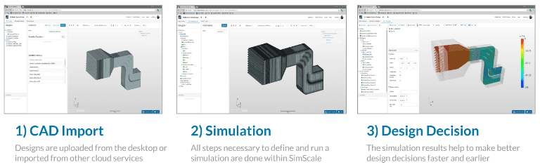
Computational Fluid Dynamics (CFD) analysis aids in understanding and optimizing the flow behavior through the complete intake system, including its air filter and ducting. In the initial design phase, a CFD analysis of the base model can help by suggesting various geometrical changes—such as guide vane placement in inlet plenum of the filter, enhanced filter utilization area, optimized sizing of filter mesh, etc., to improve the flow characteristics. The straightforward workflow—from the CAD model import to the final design decision—allows us to make critical improvements early on, which can potentially save you days of work and a substantial amount of money by avoiding later design changes or performance issues.
To practically illustrate the advantages of integrating flow simulation into your ventilation system design process, we hosted an online demo session, the recording of which can be found below.
To approach this case study, let’s first consider the two primary reasons for pressure drop in ducts:
- Friction. When air moves through a duct, it rubs against the inner surfaces of the duct and loses energy. Thus, it slows down, resulting in a pressure drop. The more it rubs, the more the pressure drops. It’s like walking down a busy sidewalk with your shoulder rubbing against the walls. The amount of friction depends on the roughness of the material the duct is made of, how it was installed, and how dirty it is.
- Turbulence. The other primary cause of pressure drop is turbulence. Turbulence is characterized by chaotic changes in pressure and flow velocity. It is the friction of air rubbing against itself. The main cause of turbulence within ducts is the turning of the air. When air flows through a 90° bend, the type of fitting that is used can make a big difference.
With the help of CFD analysis, we can visualize the appearance of flow separation in the bends, including the stagnant and dead zones. They cause the decrease in the total pressure of the gas entering the system. The strong curves in the bends are responsible for the development of secondary flows comprising counter-rotating vortices, which significantly degrade the performance of the system.
Project Overview
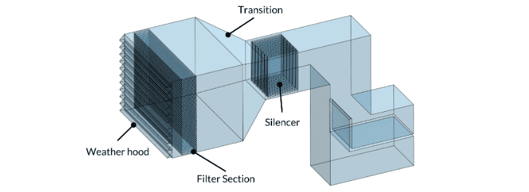
The simulation project we used is part of our public project library and is freely available to view, copy, and modify—Air Intake System Design Optimization. The purpose of this analysis was to investigate and reduce pressure drop in an air intake system. The system consists of a weather hood at the inlet through which the air penetrates. Behind the weather hood, there are thin grills of the pre-filter section, followed by the main-filter section which is modeled as porous media. The cleansed air from the filter enters the transition, leading into the silencer panels. The panel’s exit is further connected to the bend, and the flow finally exits through the two outlet openings, on which fixed-value Velocity Outlet boundary condition is applied. Specifying the air flow rate (25.1 m3/s) on the outlet more closely simulates the fact that the air is being drawn through the system.
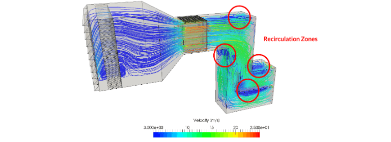
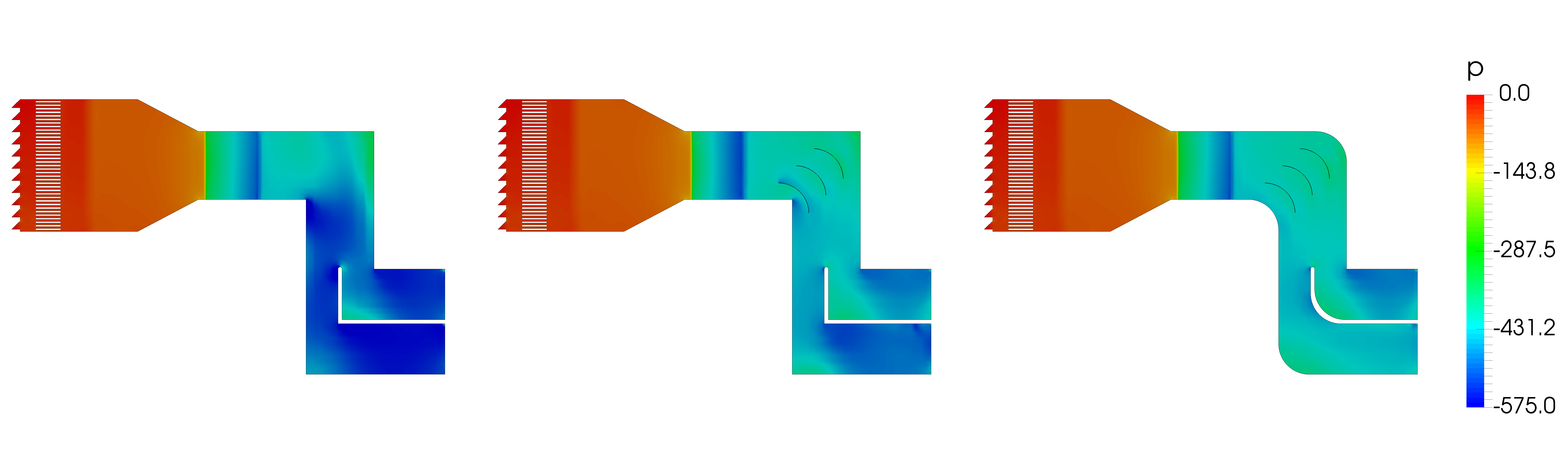
The results show where the maximum pressure drop occurs in our original design: the blue areas—the recirculation zones—in the duct part, after the silencer indicates the formation of vortices, which result in a pressure drop and wasted energy.
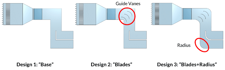
In order to find a way to mitigate this, two optimized designs were analyzed, in addition to our initial one:
1. Conventional design with sharp corners at the bend
2. Optimized design with blades (guide vanes) at the bend
3. Optimized design with blades and rounded corners at the bend
We then performed a steady state analysis with incompressible, turbulent flow.
Ventilation Design CFD Simulation Results
From the pressure contours, we can see that a variation in pressure drop between the 3 designs occurs between the bend and outlet section. This effect is the weakest for the optimized Design 3—with blades and rounded corners at the bend. Thus, it can be seen that rounded corners together with blades result in a maximum reduction in pressure drop.
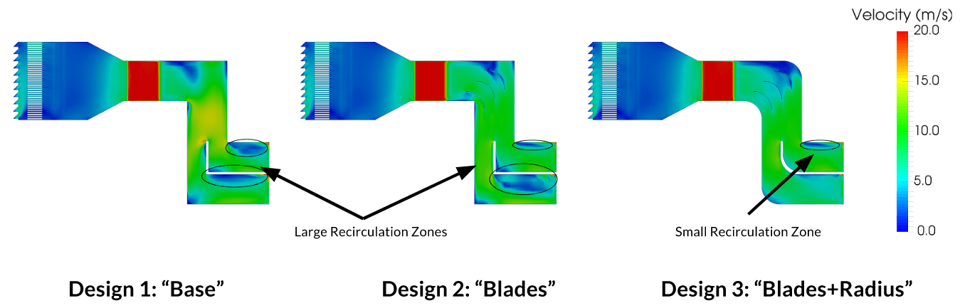
From the velocity contours, it can be seen that the recirculations are also considerably reduced in the optimized design with blades and rounded corners at the bend, compared to the other two designs.
To present the results in a more quantitative way and see how our design changes impacted the air intake system’s performance, we can look at the average pressure drop across the entire air intake system. We can see that after switching to the optimized Design 3, we were able to achieve a pressure drop of 16% or over 80Pa. If we remember the estimation of the impact of such a reduction in pressure, calculated in the paper by Khashayar Khorsand et al., it becomes apparent that adopting this design change can have long-lasting financial benefits.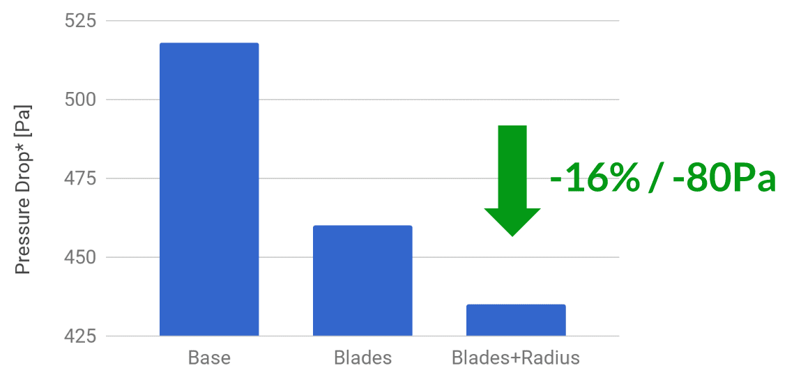
Conclusion
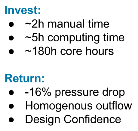
This case study illustrates how a minor design change can lead to a significant performance improvement. Very often, however, such changes never get tested or implemented, because their impact is underestimated and the manufacturing costs are too high. With simulation, however, design engineers can evaluate their innovative ideas in a matter of hours, with only a minor investment of time and manual effort on their part. The simulation we used in this study took 2 hours of manual time, 5 hours of computing time, and 180 core hours because everything ran in the cloud. As a result, we tested an optimized design that achieved a 16% pressure drop with a homogenous outflow—as well as a more efficient and reliable system overall. Over time, this will save a considerable amount of energy.
This is just one example of how an engineer can leverage CFD to improve a ventilation system design. The SimScale Public Projects library has a wide selection of simulation templates covering various aspects of HVAC and AEC, including thermal comfort, contamination control, wind engineering, and more.
Explore it by creating a free Community account.
This free infographic illustrates how architects and engineers can use CFD to virtually test and optimize building designs and HVAC systems. Download it for free.

References
- Khashayar Khorsand, S. M. H. Karimian, M.Varmaziar, S. Sarjami, Investigation of Flow Pattern and Pressure Loss of A V94.2.5 Gas Turbine Air Intake System using 3D Numerical Modeling
Other Natural and Mechanical Ventilation Resources:
- Learn about mechanical ventilation simulation.
- Read about the stack effect and natural ventilation.
- Learn how to ensure thermal comfort in buildings.


