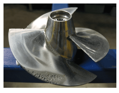
One of the leading causes of performance deterioration of pumps and turbines is cavitation, which refers to the formation of vapor bubbles inside the working liquid. Cavitation adversely manifests itself in vibrations, noise, and a drop in pump efficiency. If not correctly treated, it can cause equipment failure over time.
Access to simulation tools is critical at all design stages of pump and turbomachinery design to minimize performance issues later in product development. Simulation using SimScale can be used for cavitation modeling to understand its effect on the performance of real-life pumps.
A rotating machinery engineer working on a new product or component can import and edit their CAD model in SimScale to perform multiple analysis types such as computational fluid dynamics (CFD), structural, and thermal using automated workflows and intuitive user interfaces. A thorough treatment of the cavitation phenomenon and parametrically studying pump geometry is possible thanks to the practically unlimited computational power of engineering simulation in the cloud.
In this article, we demonstrate how to set up the process of a cavitation simulation, including how to identify cavitating flow and the essential design factors influencing the onset of cavitation, such as the net positive suction head required (NPSHR), cavitation number, and inlet sizing.
Fast and Accurate Pump Simulation
The advanced physics solvers in SimScale allow designers and engineers to study and optimize pressure drop and force behavior, evaluate fluid flow patterns, and manage cavitation effects. The SimScale Multi-purpose CFD solver is a multi-purpose analysis type designed explicitly for turbomachinery, propellers, and, more generally, anything that rotates within a fluid. It includes a robust meshing strategy that produces an automated and robust hexahedral cell mesh, using the body-fitted Cartesian meshing technique that significantly reduces mesh generation times by an order of magnitude.
It uses a finite volume-based solver optimized to handle a wide range of flow regimes, including:
- Incompressible (isochoric)
- Compressible
- Laminar
- Turbulent
The highly parallelized meshing algorithm gives a higher quality mesh requiring much fewer cells to attain comparable accuracy to traditional discretization schemes. This technique leads to faster convergence and hence, faster simulations.
The Multi-purpose analysis type simulates incompressible and compressible flow, with turbulence modeled using the RANS equations and the k-epsilon turbulence model. A powerful feature of this analysis type is the built-in parametric capability for defining velocity inlet boundary conditions. At the simulation setup stage, users can define multiple inlet flow rates simultaneously that are then simulated simultaneously; these can also be uploaded using a spreadsheet with pump curve data.
Using Simulation to Study Cavitation in Pumps
Cavitation is the formation of vapor bubbles in low-pressure and high-velocity regions of liquids. In this example of a centrifugal pump, we are interested in using simulation to inform the adverse effects of cavitation that can cause damage to equipment, such as wearing impeller vanes, erosion of mechanical bearings, seals, and valves, and unwanted noise and vibration. Cavitation can also reduce flow performance for a pump.
When the cavitation bubbles collapse, they generate shock waves that create mechanical vibration and acoustics noise. Cavitation in pumps is a critical real-world effect that SimScale factors into the CFD simulation of pumps, water turbines, marine propellers, or any rotating machine immersed in a fluid.
The compressible effects of the vaporization are modeled within the cavitation model separately from the incompressible CFD flow modeling. Since the overall flow volume is water in this example, an incompressible fluid, then incompressible flow modeling is selected. Cavitation properties of the water, or any other fluid, are characterized by setting the bulk modulus (or fluid elasticity), the saturation pressure, and its molecular weight, all defined in the materials library. The local flow characteristics, along with these material properties, determine the extent of the cavitation within the flow domain.
SimScale computes the space occupied by each phase (volume fraction), and the cavitation results are shown as the volume fraction of gas in the liquid.
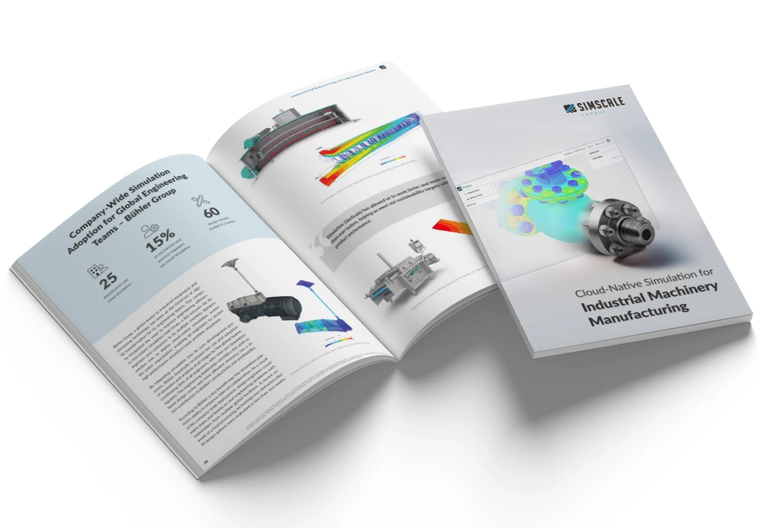
Cloud-Native Simulation for Industrial Machinery Manufacturing
Our latest eBook explores how cloud-native simulation is transforming industrial machinery manufacturing challenges into opportunities. Download it for free by clicking the button below.
Pump Simulation Setup
A simple workflow is required to complete the analysis for the centrifugal pump.
Import & Prepare Geometry
Users can import many types of standard CAD file formats and use CAD connections with tools such as Onshape, Solidworks, AutoCAD, and more. The CADmode feature in SimScale allows users to perform basic CAD operations, extract the flow volume and define a cylinder as the rotating zone within the platform.
The pump geometry is imported from Onshape. The flow volume domain is extracted using the Internal Flow Volume extraction tool in CAD mode, and a cylinder is created to define the rotating portion of the pump.
Simulation Set Up
The next step is to create a Multi-purpose analysis type simulation from this flow volume geometry. The main steps an engineer would undertake to define the simulation are to assign: the flow material, the inlet and outlet flow conditions, and the rotational velocity of the pump.
Selecting the Multi-purpose analysis item at the top of the navigation sidebar gives access to toggle the cavitation modeling and time-dependency of the simulation (whether the simulation models steady-state or transient flow behavior). For this case, the material and cavitation properties of water are already integrated into the extensive SimScale materials library. However, other fluids can be defined based on their density, viscosity, and cavitation properties and saved in the database.
The flow rate going through the pump can be defined either at the inlet or outlet face, depending on the operating conditions the engineer wants to define; this can mean the pump system can be defined by a suction flow rate, a discharge flow rate, or a specified pressure difference. The flow rate condition can also be parameterized to a progression of flow rates so that multiple simulations at different flow rate conditions can be run in parallel.
The rotational velocity of the pump blades is defined within the Advanced Concepts → Rotating zones section, where the rotation axis also needs to be specified.
In the case of this centrifugal pump geometry, the following boundary conditions have been applied:
Case A: Varying Discharge Flow Rates
- Inlet – flow rate sweep from 1 L/s to 11 L/s using velocity inlet boundary conditions.
- Outlet – pressure outlet (1 atm) boundary conditions modeling ambient conditions.
- Impeller – rotational speed around the vertical axis set to 500 radians/s
- Physics – incompressible, fully turbulent flow
Case B: Varying Suction Pressure Heads
- Inlet – flow rate of 11 L/s using velocity inlet boundary conditions.
- Outlet – pressure outlet sweep from 3.4m to 6.2m of water head pressure
- Impeller – rotational speed around the vertical axis set to 500 radians/s
- Physics – incompressible, fully turbulent flow
Meshing
The meshing process discretizes the flow domain into a finite set of cell volumes that aims to match the original geometry. Within the Multi-purpose analysis type, the workflow for generating the mesh is automated and robust in capturing varying levels of geometry detail; the user defines the level of mesh fineness on a sliding scale from 1 to 10.
The automated meshing process generates a body-fitted Cartesian mesh, ensuring the mesh quality is highly orthogonal. A manual process of defining the minimum, maximum, and target cell size is also available for further control of the process. For this centrifugal pump geometry used in this case, the mesh size was on the order of ~500K cells.
Post-processing
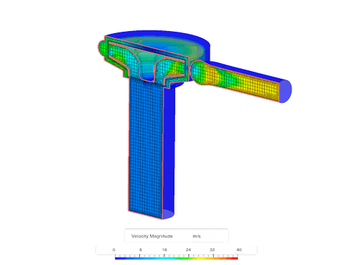
The SimScale platform’s field results visualization tool allows engineers to understand the flow behavior throughout the entire flow domain. Some significant quantities to look at for a pump application include the pressure distribution, the flow velocity along with the velocity vectors, and the cavitation effects.
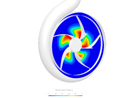
Cavitation is modeled within SimScale using the gas volume fraction quantity so the intensity of cavitation can be visualized just like any other field quantity. The use of cutting planes can give a planar view of the distribution of these field quantities, but the iso-volume feature presents the regions where specific field quantities fit within certain criteria; this can be used to get 3D insights on key flow behavior attributes that are of interest to the engineer, such as the extent of the cavitation behind pump blades.
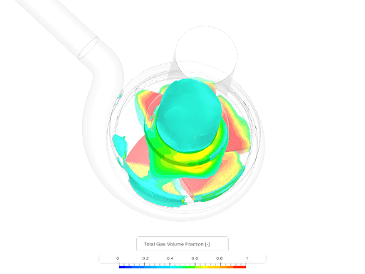
The total gas mass fraction is visualized in SimScale, shown in the image below. In a region with a high volume mass fraction, there is a high chance of cavitation developing. When the flow hits the leading edge of the impeller, it accelerates and then creates low pressure. If this pressure drops below the fluid’s vapor pressure (water), it can lead to cavitation.
In this case, cavitation is seen around the impeller extending into the inlet pipe due to air bubbles trapped in the entire volute casing.
Understanding Cavitation in Pumps
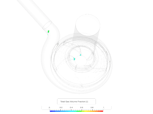
We have simulated two-pump flow rates to ascertain the adverse effects of cavitation. The images below show significantly less cavitation with a higher flow rate of 11 L/s than 1 L/s. In the latter scenario, the higher pressure at the outlet creates an intense cavitation effect around the impeller. With this simulation setup, users might continue with additional flow rates and perform an optimization study on flow rate vs cavitation propensity.
Additionally, users can duplicate the entire setup and swap the geometry with an alternative CAD model design. This step would preserve all the simulation parameters and boundary conditions, and multiple pump designs can be evaluated in parallel. CAD Geometry variants to consider exploring should include various volute casing shapes, length of inlet and outlet pipes, and even the impeller profile.
SimScale can also simulate all the points on a pump curve in parallel using the fast and accurate Multi-purpose analysis type. Manufacturers provide performance curves that tabulate static pressure, power, rotational speed, and efficiency values per flow rate conditions. This data is used for selecting and sizing pumps.
SimScale allows engineers to directly input the manufacturer’s data and simulate its performance. When designing new pumps, SimScale can calculate the pump curve for a design by running parametric studies that solve for a range of pressure/flow points. The highly parallelized algorithm allows a parametric study to run nearly simultaneously as simulating a single pressure/flow condition.
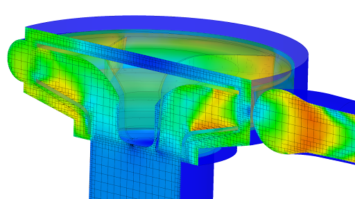
Other pump analysis types include static/dynamic loading, stress, and vibration analysis using the structural simulation capabilities in SimScale, making the platform a powerful tool for turbomachinery engineers.
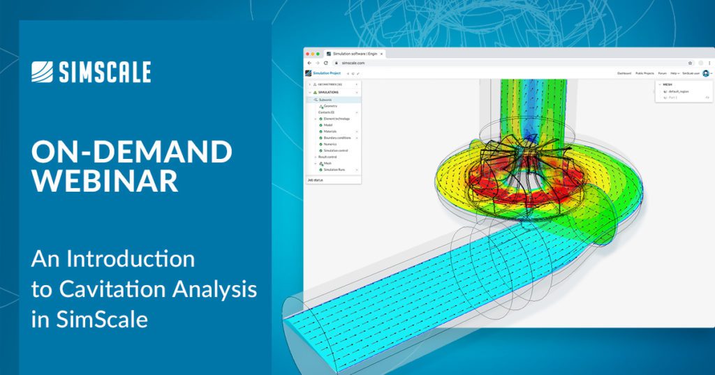
Webinar: An Introduction to Cavitation Analysis in SimScale
This on-demand webinar shows a step-by-step demo of the cavitation modeling capability available in SimScale to understand its effect on the performance of a real-life pump. Gain a thorough characterization of the phenomenon of cavitation in pumps, along with an understanding of the design factors that lead to cavitation: