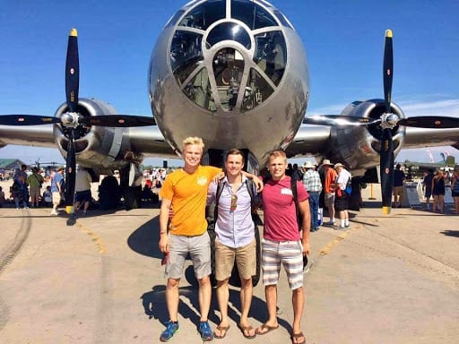
DarkAero was founded in 2017 when three brothers—Keegan, River, and Ryley Karl—left their engineering careers to pursue their shared dream of creating the best kit aircraft known to man. To this day, the Karl brothers’ ultimate mission is to engineer the ‘fastest, longest range aircraft you can build in your garage,’ which is displayed proudly on their website.
But what is a kit aircraft, and how is this possible? In this article, we will explain everything from what an amateur-built aircraft is all the way to how to test aircraft components like wings for the angle of attack, stall behavior, and lift.
What Is a Kit Plane?
If you are not familiar with it, a ‘kit plane or aircraft’ is a homemade airplane. These amateur-built planes are not for professional or commercial use, and are certified as ‘Experimental’ under the Federal Aviation Administration (FAA) or other local regulations in the United States.

This concept might sound a bit daunting if you, like me, are not an aerospace engineer. Well, actually, amateur plane-building has been around for quite a while. In fact, amateur-built aircraft initially gained popularity and momentum in 1924 with the start of the National Air Races, held in Ohio, USA.

Kit planes typically can hold 1-4 persons in-flight, and historically employed the simplest forms of construction available including wooden frames and fabric. Today, designers like DarkAero are increasingly adopting more sophisticated construction methods, using carbon fiber, fiberglass, other composite materials, as well as full aluminum techniques.
A New Kind of Kit Plane: How Did the DarkAero 1 Come to Fruition?
The Karl brothers grew their interest in kit planes as they frequently attended the EAA AirVenture event in Oshkosh, WI. After years of event re-attendance and a growing desire to find an aircraft kit that could fly faster, go further, and be more efficient than ever before possible, it became clear that the Karl brothers could no longer simply be enthusiasts; the DarkAero 1 concept was born.
Together, the Karls have backgrounds in mechanical, computer, electrical, and aerospace engineering, which has supported the development and creation of their first aircraft design, the DarkAero 1.
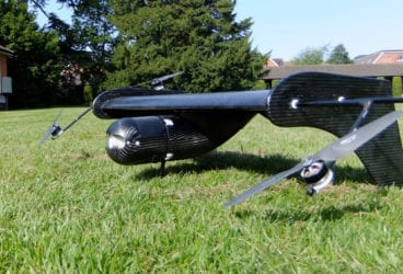
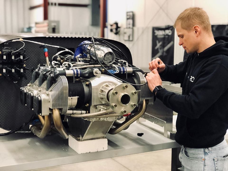
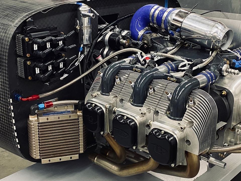
For the past three years, DarkAero has been working hard to turn their dream into a reality. Last month alone, the team made exciting progress on the remaining sections of the DarkAero 1 prototype. From mounting the engine to the airframe to manufacturing landing gear components, you can read about the latest and greatest DarkAero 1 feats from them here. Yet, since embarking on this aerodynamic adventure, one question always seems to surface for DarkAero: how can they assure potential customers that their kit plane will fly?
Determining DarkAero 1 Can Fly
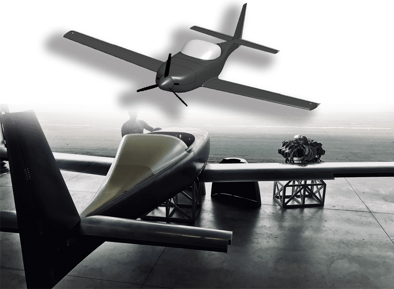
For starters, the DarkAero 1 was created with a very specific purpose; to be the best kit plane, and utilize the available technology more efficiently than ever before possible. The aircraft can hold two passengers, has a cruising speed of 275 mph, a 1700 mile range, and even boasts retractable landing gear.
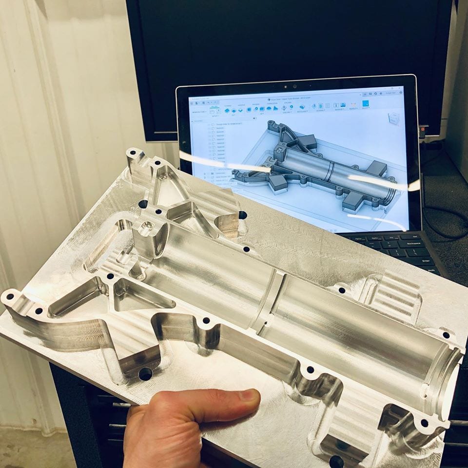
In order to design, test, and evaluate the DarkAero 1’s flight performance and behavior, the team used a range of engineering tools. These tools include engineering equations, wind tunnel testing with 3D printed models in the University of Wisconsin – Madison wind tunnel, and online CFD simulation software (SimScale). In the remainder of this article, we will focus on how CFD simulation results have benefited DarkAero by determining flight behavior attributes, such as lift conditions and wing stall characteristics.
How Can We Evaluate Wing Stall?
For aircrafts of all shapes and sizes, there is always a maximum lift coefficient or condition that needs to be met for takeoff and landing, as well as for periods during flight with reduced speed. This lift is generated by the aircraft’s wing, and is related to its angle of attack, or the angle that it is flying into the oncoming airflow.
At a shallow angle of attack, the wing produces minimal lift and the airflow around the wing follows the contour of the wing surface. There exists a critical angle of attack where the wing produces the maximum lift before stall occurs. Typically, the angle of attack for maximum lift is around 15 degrees, but can fluctuate significantly depending on the fluid type (in this case, air), airfoil shape, and Reynolds number.
A stall occurs beyond the point of where the wing achieves maximum lift and it is characterized by a reduction in lift as well as airflow separating from the surface of the wing. In terms of fluid dynamics, a stall is the result of a reduction in the lift coefficient generated by an airfoil as the angle of attack increases. In fixed-wing flights, stalls can be experienced as the pilot increases the wing’s angle of attack, while exceeding its critical angle of attack (which may be due to slowing down below stall speed in level flight).
Despite how it sounds, a ‘stall’ does not, in fact, mean that the engine has malfunctioned or that the plane has stopped moving—this effect is palpable even in an unpowered glider aircraft.
In general, aircraft engineers want to design a wing so that it stalls in a gentle, predictable manner. Ideally, the stall should start at the root of the wing and progress outward towards the wingtips. The ailerons, which provide roll control for the aircraft, are positioned outboard on the wings, so it is best to have the wing tips stall last so that roll control is maintained.
This gradual, progressive stall provides an indication to the pilot that a stall is approaching. If the wing is not designed to provide this indication, a sudden loss of lift could happen without warning. A loss of lift without warning is dangerous especially at low altitude during takeoff and landing because there is little time for recovery. In order to assess and confirm correct stall behavior for DarkAero 1, the team turned to SimScale.
Evaluating Angle of Attack and Wing Stall Behavior with SimScale
The team at DarkAero used CFD through SimScale to virtually “fly” the wing of the DarkAero 1 at a range of different angles of attack to determine the angle of maximum lift and where stall occurs. Once the angle of maximum lift was determined, the Karls further refined their simulation in the region a few degrees before and after stall, in order to then predict how the stall would develop on the wing.
From the early design stage, the wing of the DarkAero 1 was designed to have a progressive stall that initiates at the root of the wing, progressing outboard towards the wingtips. Through analyzing simulation results from SimScale, they were able to design the DarkAero 1 wing so that it stalled effectively as planned. In the video below, Ryley Karl explains how SimScale was used to evaluate the lift coefficient and stall behavior for DarkAero 1.
The video, existing on DarkAero’s YouTube channel, gives greater insight into how they used cloud-based engineering and CFD simulation tools, from Onshape to SimScale, to help design the wing for DarkAero 1. Below, we’ve transcribed the highlights for a quick summary of what the results entailed.
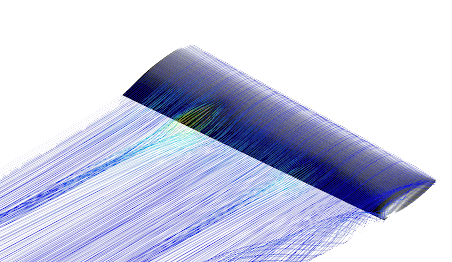
The Angle of Attack at 0°: CFD Analysis

First the team looked at the wing flying at a shallow angle of attack, as one would see in high speed cruise flight. To keep things simple, the above image and following images concentrate on just the right wing, with the rest of the air frame removed. The airflow streamlines over the wing show a clean and uniform pattern over the wing, following its contour. This is referred to as the airflow being attached to the wing.
The Angle of Attack at 10°: CFD Analysis

At 10°, the airflow is still attached to the wing surface and the wing is generating more lift.
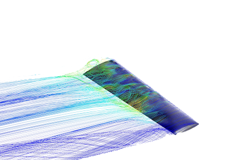
The Angle of Attack at Initial Stall: CFD Analysis
At an even higher angle of attack, the first warning signs of a stall can be clearly seen. A small pocket of separated airflow starts to appear at the root of the wing. This is what the team wanted to see, as they designed the wing to stall in this manner at the root first.
The Angle of Attack at Flight Stall and Beyond: CFD Analysis
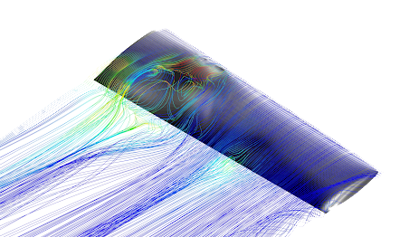
As they continue to increase the angle of attack even further in different simulation runs done in parallel on SimScale, they see the stall progress outboard along the wing towards the wingtips. The inboard portion of the wing stalls first, as you can see by the separated airflow near the root of the wing.
In one simulation run, the team crept up a bit higher in the angle of attack, and the majority of the airflow separates from the wing and the total lift generated by the wing is seen to be dropping. The wingtips try to hang on to the very end of the stall, which is, again, as desired. With these results from SimScale, DarkAero can simulate stall and start to build a predicted model of the stall behavior.
Next Steps for DarkAero
As DarkAero continues down the road to production for DarkAero 1, continued collaboration is planned between the team and SimScale to evaluate other aspects of the design. Stay tuned for more details, coming soon.
Interested in Learning More About CFD and Aerodynamics from SimScale?
- World Record Holder in Downhill Skateboarding is Using Simulation to Optimize Aerodynamics
- Aerodynamics of Road Vehicles in the Computational Domain: A Summary
- Building Aerodynamics 101