From Concept to Hydrogen in Three Months: How Fourier Designed a Next-Generation Electrolyzer Stack with SimScale

$40K–$60K in prototyping costs avoided
Complete stack design delivered in under 3 months


Fourier is a hydrogen electrolyzer startup building next-generation proton exchange membrane (PEM) electrolysis stacks for clean hydrogen production. The company takes a first-principles approach to electrolyzer design — developing bipolar plates, sealing systems, and flow architectures in-house rather than relying on established commercial stack designs. The goal is hydrogen infrastructure that is technically rigorous, manufacturable at scale, and commercially viable.
The company is at an early but decisive stage: validating electrolyzer stack architectures that are not only technically rigorous but manufacturable at scale and commercially viable. The company’s guiding philosophy is one of engineering audacity: the conviction that hard technical problems in hydrogen infrastructure deserve to be attacked directly, with rigor, rather than deferred or designed around. The engineering team operates with a startup cadence of building quickly, failing fast, and iterating efficiently, and simulation is central to how they move at that pace without accumulating expensive physical prototyping debt.
The engineering challenges Fourier faces are significant. PEM electrolyzers operate at high differential pressures — cathode pressures exceeding 25 barg — in a highly corrosive environment. Sealing these systems reliably with thin plate geometries and shallow glands requires seal designs that go well beyond what standard engineering handbooks can predict. Alongside the mechanical challenges, the electrochemical flow architecture must ensure that every cell in the stack receives uniform reactant distribution, or localized membrane starvation and failure will follow.
Jordan Polischuk, P.Eng., is a Senior Mechanical Engineer at Fourier focused on electrolyzer stack design. His background spans fuel cell and electrolyzer development, including a previous role at Ballard Power Systems where he worked on heavy-duty fuel cell applications. At Fourier, Jordan owns the mechanical design of the stack: bipolar plates, sealing systems, and the simulation workflows that underpin every design decision.

“Standard seal design references assume gland depths and plate thicknesses that we simply don’t have on our bipolar plates. We had to build our own understanding of how these seals would behave from first principles, and SimScale with Marc gives us the environment to do that.”
P. Eng., Sr. Mechanical Engineer, Fourier
Fourier’s engineering program places demanding requirements on simulation software. The team needs to run nonlinear structural analysis on hyperelastic materials using advanced solvers, CFD on complex geometries containing features spanning a wide range of length scales, and parametric studies across dozens of design variants.
SimScale delivered on both counts. Jordan had benchmarked the platform’s CFD capabilities against experimental data for small-channel geometries, as found in fuel cell and electrolyzer stacks, and found the multi-purpose solver both accurate and efficient on problems that push conventional meshing tools. For the nonlinear structural work, the Marc solver handled the hyperelastic material models and contact mechanics that seal design in shallow glands demands. “These are not analyses you can run with a basic FEA package,” Jordan notes. “You need a solver that handles large deformation, contact, and nonlinear material behavior properly.”
The cloud-native architecture removed a practical constraint that would otherwise have limited how the team could work, delivering instant accessibility and scalability as the engineering team needed it. “We got up and running extremely quickly with SimScale, with no IT overhead to worry about, and we were immediately running simulations and driving our design forward,” Jordan adds.
SimScale’s ability to cover FEA and CFD within a single platform also mattered. Fourier’s engineering work crosses both disciplines — every stack iteration involves mechanical seal design and fluid flow validation. Managing two separate licensed tools, two separate workflows, and two separate learning curves was not an option Jordan wanted to take. With SimScale, the team moves between physics domains without changing platforms, and without the overhead of maintaining multiple software environments.
When Jordan joined Fourier, the initial plan was to use square die-cut seals — a common starting point, but one with a fundamental problem. “Those are going to be problematic,” Jordan recalls thinking when he first saw them. Standard handbook rules for O-ring compression assume relatively deep glands and standard cross-sections. In thin electrolyzer plates, where gland depth is constrained by plate thickness, the standard rules break down. There was no analytical shortcut to finding a geometry that would work.
The challenge was compounded by the operating conditions. The cathode side of Fourier’s stack operates at very high pressure — demanding not just adequate contact pressure, but sealing redundancy in case of a localized failure. The design also needed to survive manufacturing variation without either hydrolocking at the generous tolerance extreme or losing contact pressure at the tight extreme. And it needed to be stable: shallow glands provide little lateral support for the seal, and a geometry that looks stable in static compression can roll or flop when pressurized, causing immediate leakage.
With the Marc nonlinear structural solver in SimScale, Jordan began working through seal geometries systematically. The team tested approximately seven distinct design families — ranging from simple square cross-sections to more complex profiles — using contact pressure as the primary performance metric. As Jordan explains, “Contact pressure from SimScale is a direct measure of how much we should be able to seal to. We’ve done tests to show that it matches up. It’s really easy: you compress a shape, you get a contact pressure output, and that number can go straight into a table.”
The team narrowed the design space from multiple design families to a preferred general geometry designed to produce multiple distinct contact patches of high pressure when compressed — a redundant sealing arrangement so that if the primary contact patch developed a leak, another patch would capture it.
Jordan ran parametric studies to fine-tune the dimensions — height, radius, and cross-sectional proportions — across roughly 10 to 15 iterations per seal cross-section. The final electrolyzer design uses three distinct seal cross-sections, placing total simulation runs at approximately 40 analyses across the design cycle.

The final seal geometry was selected to satisfy two key criteria. First, the compressed geometry needed to remain stable under applied pressure, neither rolling in the groove nor flopping when the stack was pressurized. Second, it had to remain stable across the full range of possible machining tolerances of the shallow gland.
Jordan first ran parametric most material condition (MMC) and least material condition (LMC) simulations to verify performance across the full tolerance range. This sensitivity analysis is an important step, confirming the design would neither lose contact pressure if the gland (the space the seal sits in) is at the generous extreme of tolerances, nor hydrolock at the tight one, where the seal essentially runs out of space to deform under load. “These simulations became essential for working out the tolerances we could accept from suppliers, so we used the simulation data to set those requirements”, Jordan explains.


The analysis then moved on to two-step loading simulations — compression followed by applied pressure — then verified that the seal would not roll or flop in the shallow groove under operating conditions. The simulation confirmed that the chosen geometry remained stable throughout the load sequence, and the team was able to move forward with confidence that a single physical prototype would suffice.
“We didn’t want to test multiple shapes the old way. We did it all in SimScale and only ended up cutting a few tools in the end. That’s what simulation-driven design should look like.”
Jordan Polischuk
P. Eng., Sr. Mechanical Engineer, Fourier
PEM electrolyzer flow channels are almost small enough to be considered microfluidic devices. Aspect ratios of the internal channels are extreme, mesh generation is difficult, and the computational requirements for accurate results are high. Jordan had benchmarked SimScale’s CFD capabilities specifically for this type of geometry, validating the Multipurpose solver against experimental data for small-channel geometries and finding it both accurate and efficient on problems that push conventional meshing tools.
In a PEM electrolyzer, water is consumed at the anode as it is split into hydrogen and oxygen. Each flow channel must receive a minimum mass flow of water to sustain the electrochemical reaction — if any channel is starved, the membrane in that region overheats due to dehydration and can fail catastrophically. Ensuring uniform flow distribution across all channels is called “flow sharing,” and it depends heavily on channel geometry, header design, and the inlet flow conditions.
To validate the CFD model before applying it to Fourier’s proprietary channel design, the team modeled the NREL 25cm2 High-Pressure Low-Temperature Electrolysis Cell Hardware reference geometry, where experimental pressure drop and flow distribution data are published (Wrubel et al., 2023, DOI: 10.7799/2205626). The SimScale Multipurpose solver matched the experimental results, giving the team confidence that the model would transfer accurately to their own geometry.
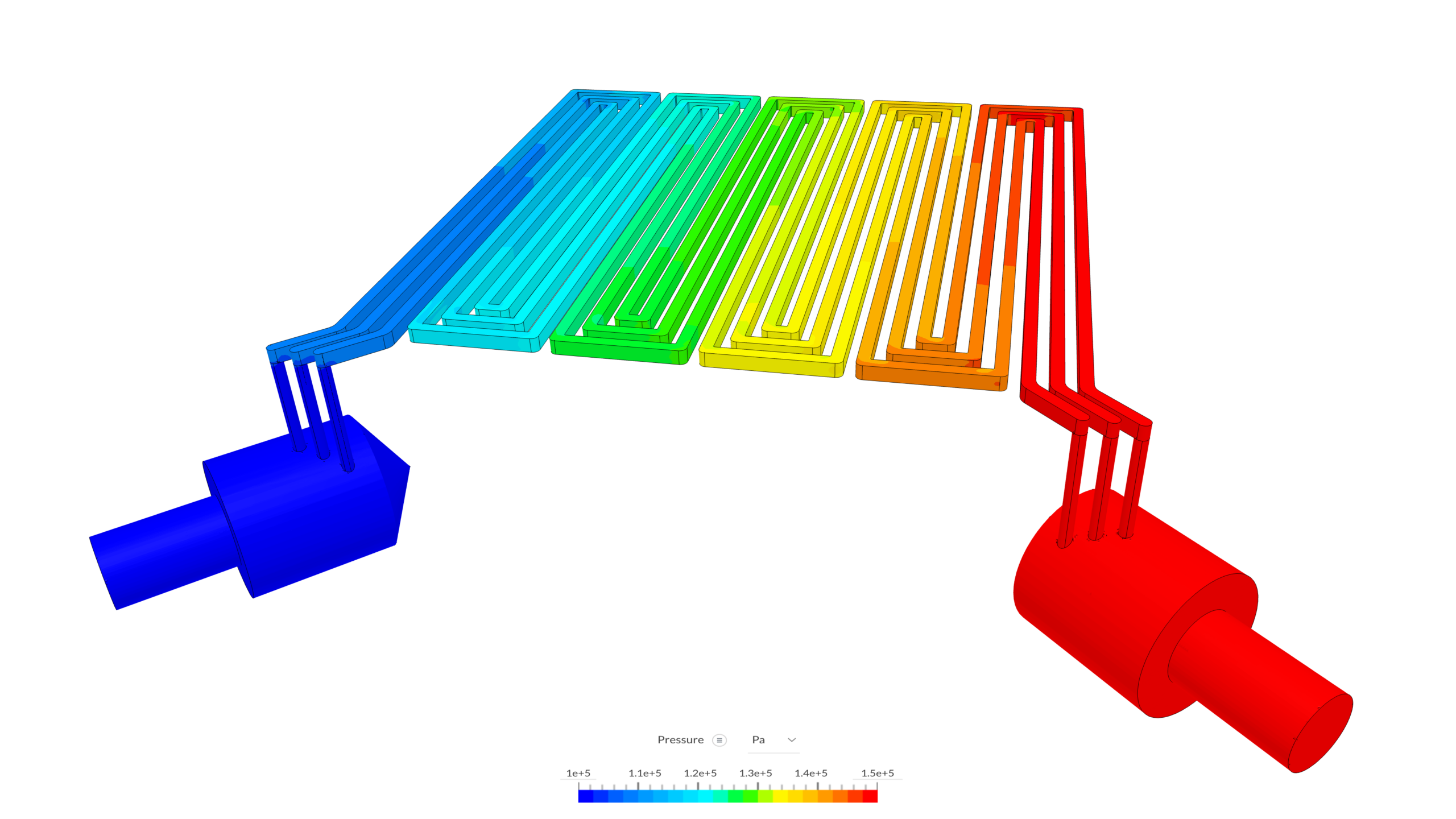
Jordan then iterated through channel and unit cell geometries, using velocity and pressure distributions to evaluate flow balancing through the individual channels. “The first priority is to make sure every channel has flow within a certain range of one another,” he explains. “Once we have that, then we can get into fine tuning and more detailed CFD analysis that measures the species concentrations”.
Crucially, the CFD workflow enabled Fourier to finalize a channel geometry that balanced pressure drop requirements against the minimum threshold for uniform reactant delivery to the catalytic active sites, before any physical manufacturing.
Fourier’s first in-house electrolyzer stack went from initial concept to a working hydrogen-producing assembly on the test bench in under three months. That timeline is roughly half of what Jordan estimates the process would have required without simulation-driven design.
As well as shortening the development cycle, using simulation lets the team simultaneously explore more design options while reducing the number of physical prototypes built. In the case of the seal design project, Jordan estimates that a traditional design process validated by physical testing, and exploring a limited number of design options, would cost in the region of $40,000–$60,000 more than the simulation-driven approach.
Looking ahead, Fourier plans to expand its SimScale use into conjugate heat transfer (CHT) modeling and hydrogen dilution estimation within the system enclosure. Both simulation workstreams support the path toward UL certification, the North American safety standard required for commercial hydrogen equipment deployment. With each subsequent electrolyzer iteration, the validated models built during this first design cycle will serve as the foundation for faster, more confident design decisions as the company moves forward.
“SimScale acted as a force multiplier for our team. It enabled engineers who aren’t simulation specialists to run advanced FEA and CFD, de-risked our prototype program before we spent a dollar on manufacturing, and preserved capital we would otherwise have burned on physical trial and error. For a startup, that’s game changing.”
Jordan Polischuk
P. Eng., Sr. Mechanical Engineer, Fourier
Set up your own cloud-native simulation via the web in minutes by creating an account on the SimScale platform. No installation, special hardware, or credit card is required.
Subscribe to our newsletter
By subscribing you agree to with our Privacy Policy
Product
Solutions
Resources
Sign up for SimScale
and start simulating now


