Used across a wide range of applications such as electric vehicles, portable devices, and power storage, battery cells often are the bottleneck when it comes to the performance of a whole system. Both the power and energy density that these components carry will determine paramount system characteristics, such as the power/mass ratio or the available range of a car, for example. In this article, we will explore the main challenges that come with designing battery cooling systems and the importance of thermal management therein.
Battery Cooling: What Are the Challenges?
There are many different rechargeable batteries available on the market, varying not only in energy and power density but also in production and maintenance cost, runtime, safety, reliability, and overall life cycle durability. These types of batteries include Nickel Cadmium (NiCd), Nickel-Metal Hydride (NiMH), Lead Acid, Lithium-Ion (Li‑ion), and Lithium-Ion Polymer (Li‑ion polymer). More information on their respective power and energy density as well as their main domain of application can be found on circuitigest.com and batter university.com.
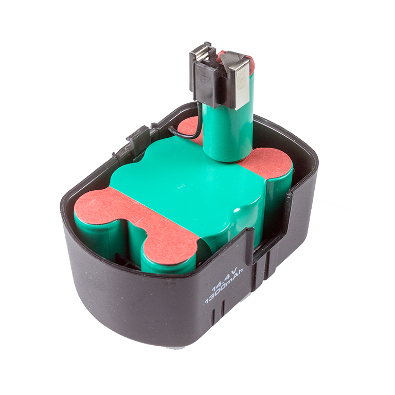
© Raimond Spekking / CC BY-SA 4.0 ( source )
Once a battery technology has been selected for an application, there are a few crucial steps in the design of the battery pack itself. These steps include the overall electric design in order to achieve the right voltage, power, and energy in balance with the cycle life, reliability, and safety.
The first step includes both the mechanical and structural design of the pack. The final design must be able to withstand a variety of vibrations, pressure, shock, and crush loads under specific conditions.
Additionally, the thermal design aims to maintain the cells within a given operating temperature range so that their longevity, performance, and safety is guaranteed. This last design consideration, applied to Lithium-Ion (Li‑ion) is the main focus of this article.
Battery Cooling: The Importance of Thermal Management
Batteries, just like humans, are happiest when kept at room temperature, both for working and resting cases. Li-ion cells and other battery technologies such as NiCd and NiMH react and perform differently with respect to the ambient temperature.
For this reason, many manufacturers chose the operating temperature for the battery specifications to be 27°C. A battery will have a better performance at an elevated temperature, but at the cost of a shortened lifecycle if the exposure is maintained over a long period of time. The graph below shows an example of a reduction in the voltage value with lower temperatures of a standard 18650 Li-ion battery.
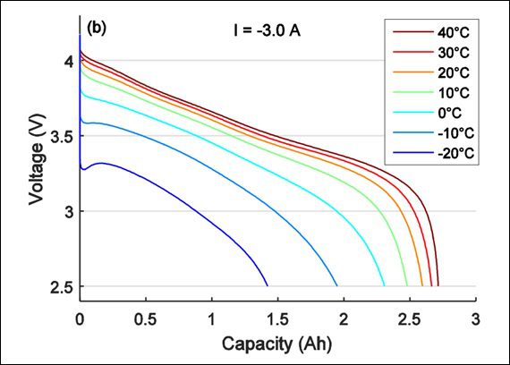
Cell type: Panasonic NRC18650PD, 2.8Ah nominal, LiNiCoAlO2 (NCA) (source)
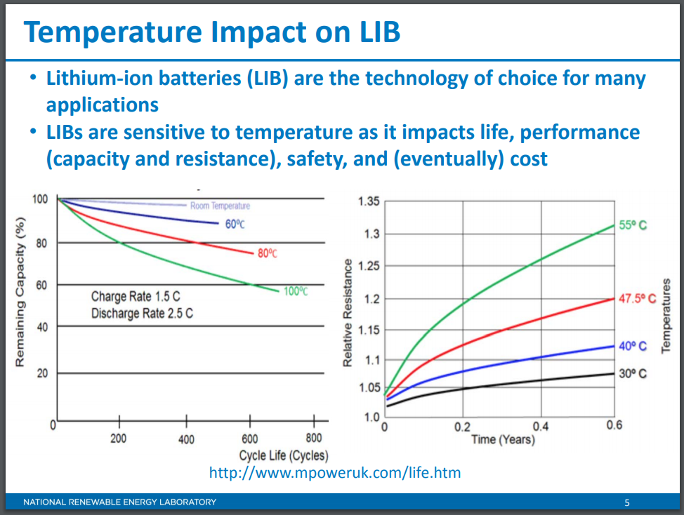
On the other end of the spectrum, at low temperature, the capacity rapidly decreases with the temperature. For example, a battery will typically deliver at –18°C only 50% of its capacity at 27°C. This is because lower temperatures affect the battery’s electrochemical reaction rate.
Many embedded Li-ion battery packs found in high-end portable devices are required to perform under harsh environmental conditions, ranging from -40°C to +80°C, like in military grade sensors. In such cases, unique design strategies and consideration must be deemed to produce sufficient cooling.
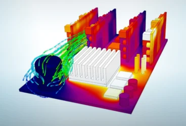
Different types of cooling strategies can be used, depending on the operating conditions and cost of manufacturing and maintenance. They range from liquid cooling, which is a very efficient type of cooling, to air cooling, which is not as efficient but a cheaper option because it is easier to implement. Air cooling can be performed through mechanical means, by a fan for example, or simply rely on the density-driven flow of air at varying temperatures, also known as natural convection.
vimeo.com
Maintaining temperature uniformity throughout the entirety of the battery pack is also crucial for the engineer to look at during the design stage. This notably impacts the overall efficiency and prevents early deterioration, safety issues, and in extreme cases, thermal runaway or even explosions. In other words, if there is a high-temperature range across the whole battery pack, then there will be a strong electrical imbalance and therefore the overall performance will suffer.
The Use of CFD as a Numerical Prediction Tool for Thermal Management of Battery Packs
When designing battery packs and their respective casings, manufacturers must assess the thermal performance of their designs under working conditions by building actual prototypes and run extensive series of tests, often over a long period of time, always at a high cost. During these tests, a myriad of sensors and other measuring devices are used to accurately record temperature, pressure, and velocity values. These recorded values are then compiled to verify whether the batteries are kept within the manufacturer’s recommended temperature range.
As part of a design process, whether it is at the evaluation phase, development phase or even the validation of an existing design, the use of numerical prototyping through the use of 3D CAD and computational fluid dynamics (CFD) has been shown to alleviate the cost, effort and time implied with physical prototyping.
With CFD cloud-based thermal tools available such as SimScale, numerical simulations can be easily performed from a standard internet browser, using the power of the cloud for safe, fast, and multiplied computational power as well as unlimited data storage.
Another advantage of numerical prototyping is that manufacturers can test multiple designs iterations, to identify the optimal layout that reduces both material and manufacturing costs, without sacrificing the performance of their product.
Our Case: Active Cooling Designs for LI-On Batteries
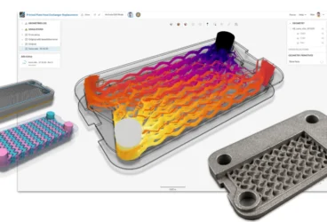
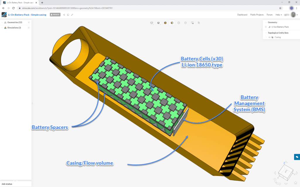
In this SimScale project, inspired by this article on cooling effectiveness, a CFD thermal analysis is used to predict the temperature of 30 commercial Li-ion 18650 cells under multiple casing designs and inlet flow conditions. The goal is to find the minimum cooling power so that the cells are kept below 40°C.
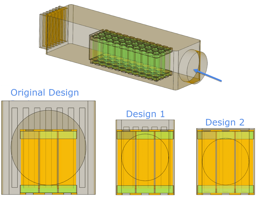
This analysis uses the model created by user “Nilesh” on GrabCAD and represents a 10s3p ( 10 rows of 3 cells) of Li-Ion cell battery pack and a Battery Management System “BMS” represented by an electronics unit board at the extreme of the battery pack. The first proposed design of the casing hosting this battery pack consists of an 80mm cylindrical air intake, a straight 400mm rectangular mid-section, and vertical outlets vents. The complete model is shown below after being imported on the SimScale platform.
In this project, both solid conduction and flow convection heat transfer mechanisms are modelled using our conjugate heat transfer solver. The thermal properties (conductivity, density, and specific heat) of the battery cells themselves, the BMS board, and the battery will significantly impact the temperature distribution within the cells.
The gravity direction was enabled. Material properties were then assigned to the components of the geometry. The cavity of the casing was defined as a volume of air. The solid components are the battery cells, to which the thermal properties were previously calculated and based on the properties of nickel. The battery spacers were assigned with ABS and the BMS board as PVC. For this simulation, the walls of the casing were considered adiabatic which means that the heat exchange at these walls wasn’t taken into account.
Like in every numerical simulation where partial differential equations (PDE) are solved, a number of known conditions of the flow and power are required for the simulation to be run. The known operating conditions were assigned as velocity and temperature at the inlet and pressure at the outlet so that they are open to the air like in real-life conditions. Multiple air velocity values were simulated simultaneously to find the minimum value leading to a battery cell temperature below 40°C. The starting point chosen is 4m/s at 23°C.
This project assumes that each cell generates 2.75W of thermal output power. This value was previously determined in this article which uses the same type of cells and a similar setup. The simulation is then ready to be run, and takes about 1 hour to complete.
Results and Design Decision
- Why is this design not efficient in achieving a safe operating cell temperature?
- How can the geometry be optimized to cool the cells better?
- Is there a potential to improve the design?
Evaluating the cooling effectiveness of the casing, one can naturally start looking at the overall temperature distribution. With an inlet velocity of 4m/s and shading the results by temperature, we can see that the peak value was 128C. This is 90C above the maximum recommended temperature of 40C and is currently a design failure.
These two result values indicate that either the design is poor for sufficiently cooling the cells or the inlet velocity is too low.
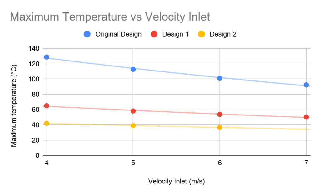
As mentioned previously, simulations with different inlet velocities are run simultaneously in order to obtain a value for the minimum inlet air velocity required. Therefore, the maximum temperature value for the battery cells for each air velocity value can be plotted and we can easily visualize which operating condition is OK.
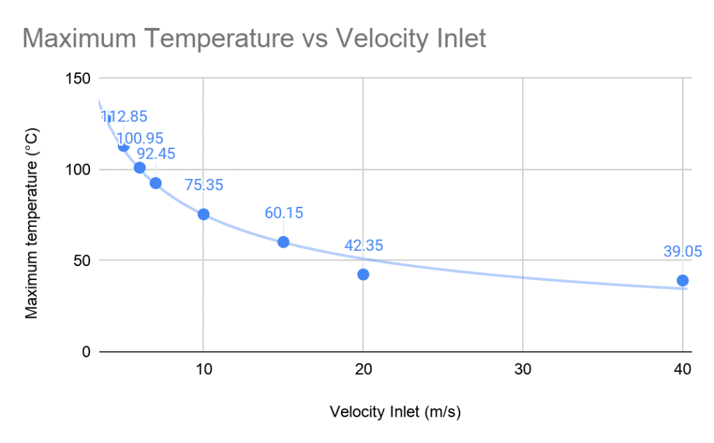
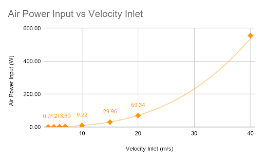
One can note that only very large inlet velocity values ( +35m/s ) will result in an acceptable temperature at the cells, and in practice could hardly be achieved by a standard fan/blower. The second graph denotes that the airpower input grows exponentially with the velocity values. This means that to cool down the battery pack by a couple of degrees in the higher velocity values, a large amount of power is required.
This can be explained by looking at the air velocity at the midplane, at 5m/s, and 10m/s velocity inlet.
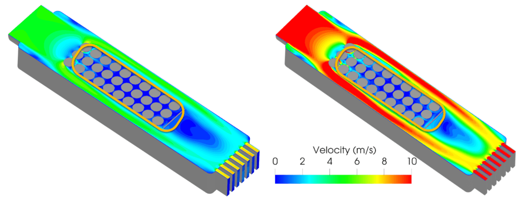
It is well known that parts are more effectively cooled when the air passing them is faster. In this case, as the air would always choose the path of least resistance from the inlet to the outlet, one can see that higher velocities don’t encounter much of the cell’s hot surfaces and therefore very little cooling effect takes place.
The central row of cells is with relatively low velocities (<1.5m/s). This gives an explanation as to why such high velocities are necessary to cool down the battery cells below the acceptable temperature. One can conclude that such gaps around the battery cells contribute to a very poor cooling capacity of the casing design.
What Changes Should Be Made to the Proposed Battery Cooling Design?
We learned that the central row is too hot, and we also saw that a lot of air simply passed around the outside of the cells, taking the path of least resistance. Based on these observations, two new designs are proposed. They both include a much narrower passage on the sides and upper part of the battery pack. The difference between the two designs is the upper gap size. The new designs have a smaller inlet diameter of 50mm (previously 90mm).
These designs can be simulated simultaneously using the same parameters (material and boundary conditions) and their results processed to be compared.
Battery Cooling Design Iteration Results Comparison
Comparing the maximum temperature of the battery packs in each design, at different inlet velocity, design 2(with the narrowest passage) achieves the acceptable cooling performance, at an inlet velocity condition of 5m/s. The maximum recorded temperature is just below 40°C, at 39.09°C, the lowest temperature is 28.35°C (range is 10.74°W).
The maximum temperature comparison chart shows a significant difference between the original design and the new design iteration, highlighting a better cooling performance for the new casings.
When looking at the required air input power for each design, we have to be careful when reducing the air space too much as it means that the power necessary to move the air through the system will be prohibitively expensive.
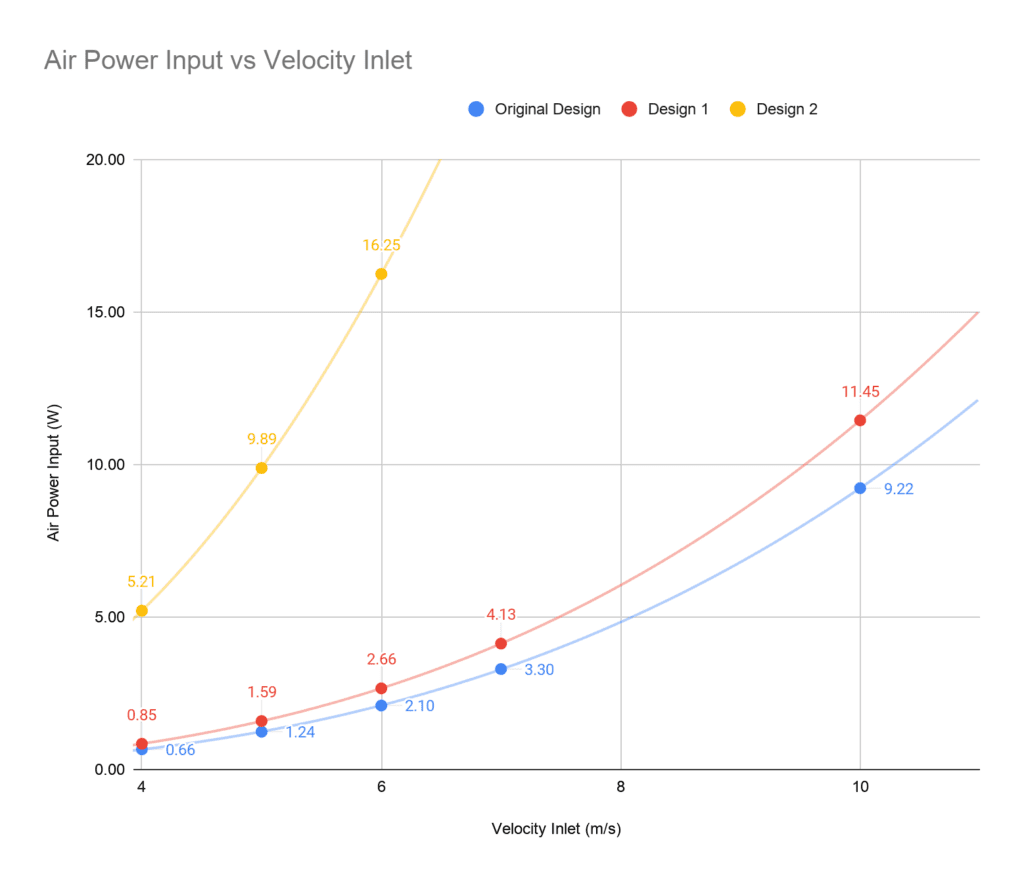
Looking at the satisfactory design and operating conditions of 5m/s, the corresponding air power required is about 9.81W. With this velocity and wattage, it is easy to select the correct fan, so that we would choose the fan that can operate most efficiently.
In comparison, design 1 would reach a similar temperature (~39°C) at the battery cells for 15m/s (36.79W).
Conclusion
Maintaining battery packs within a specific temperature range is an essential aspect to guarantee the lifespan, reliability, and safety of such components.
The cooling performance assessed in this project includes:
- The temperatures reached by the battery pack cells.
- The power necessary in order to achieve such a temperature.
The importance of forcing the air to flow at high velocity between the cells has been highlighted in the proposed designs. These improvements include narrowing the gaps on either side of the battery pack, as well as the upper gap. This way, more air is forced around the cells and therefore heat transfer can occur at the cell surfaces.