LEDs consume far less energy than any other lighting solution on the market, making them an economically and environmentally sound choice. There are several key aspects for design engineers to consider when optimizing their lighting systems, from LED heat dissipation to methods of active cooling.
The first step in optimizing LED performance for LED lighting is to understand the key components of a typical LED fixture. LED manufacturers usually produce a complete LED package, which includes 4 main components — a die, a phosphor, a substrate, and a lens. The die is the semiconductor that emits blue lights when an electric current runs through it. Multiple dies can be mounted on an aluminum or ceramic substrate. In most applications, white or yellowish light is required, therefore phosphor is applied, either directly onto the die or mixed in the lens. The phosphor particles emit white light when the blue light reaches them. The light emitted is extracted and directed by the lens.
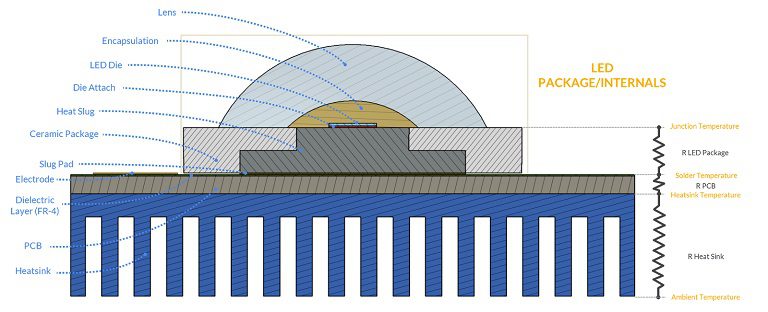
The LED package is typically mounted on a printed circuit board (PCB) with thermal interface material (TIM) paste. Lastly, a heatsink is attached to the PCB to dissipate the heat away from the LED package and toward the ambient air through conduction, convection, and radiation. Engineers can simulate heat sink designs to optimize this thermal path for specific LED configurations.
Although LEDs are, on average, six times more efficient than traditional incandescent light bulbs, there is still a considerable amount of heat converted from the electrical energy applied to the device. Unlike Edison light bulbs, where heat waste is radiated, the heat generated by LEDs is conducted. This heat must then be moved away from the device to preserve its LED performance.
LED Junction Temperature: What Is It and Why Does It Matter?
The temperature at the junction between the LED die and the substrate it is on is referred to as junction temperature. This junction is usually the highest temperature in the device making it a suitable value to indicate heat dissipation performance. Today’s LED packages are designed with conductive heat paths to move heat away from the junction point to the solder point. The solder point is located at the interface between the LED package and the PCB and/or a standalone heatsink.
The effectiveness of internal heat paths is indicated by the LED’s internal thermal resistance. The lower the internal temperature the higher the quality of the LED, thermally speaking. When designing a LED fixture from a thermal management perspective, it is essential for the design engineer to access the value of thermal resistance. This value will be used by CFD solvers to accurately determine the temperature of the LED and verify if the device has exceeded the maximum limit recommended by the manufacturer. In modern LEDs, it is standard that junction temperatures reach up to 100°C and beyond. The ambient temperature, thermal resistance between the LED junction and its surroundings, and the power dissipated by the chip all impact its value.
What Are the Effects of Poor LED Heat Dissipation?
As a general principle, when LEDs heat up, their efficiency drops. There are two primary reasons why maintaining a low temperature is critical to LED performance.
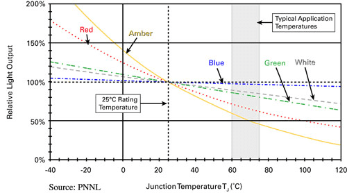
The first reason is that the light output of the LED degrades significantly with higher temperatures. This phenomenon is particularly noticeable with red and amber wavelengths. The graph below illustrates the typical decline in relative light output over temperatures at different colors.
The second reason is that the light output falls gradually over time. This gradual decrease is accelerated by higher temperatures. Below is a typical example of light output versus the working hours of an LED at different temperatures. We can see that a drop of 11°C translates to an extension of 25K hours of working life!
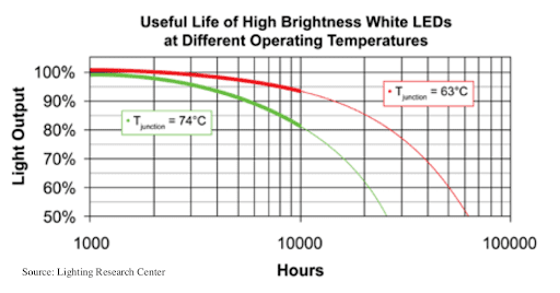
Source: Lighting Research Center
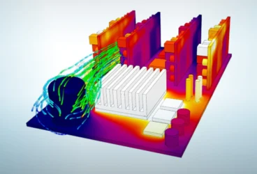
As LED systems can see their life shorten significantly when exposed to prolonged heat, testing of thermal aspects is crucial. Physical testing, which includes setting up test benches, laying out thermocouples, and following standardized testing procedures is expensive and time-consuming. Thermal CFD simulation offers a solution for those wanting to optimize their LED lighting design quickly and efficiently, without sacrificing results accuracy, and reliability.
Thermal Design Considerations
Any LED fixture must be designed to keep LEDs cool by reducing heat resistance from the LED to the ambient air. This is done by considering and optimizing all three modes of heat dissipation — conduction, convection, and thermal radiation, in any part of the fixture design.
1. LED Spacing and Arrangement
Designers often want to reduce the spacing between LEDs on a PCB to produce compact LED fixture designs. However, this means an increase in thermal power density and, therefore, a rise in the temperature of the LEDs, as seen below.
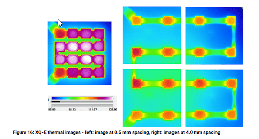
LED manufacturers often provide a recommended spacing between LEDs and indicate the rise in temperature one can expect to see when spacing is reduced by a certain amount.
In terms of LED arrangement on the board, studies have shown that uniform and symmetrical chip arrangement provides a similar heat load whether it is rectangular, hexagonal, or circular.
2. LED Module Choice
LEDs come in a wide range of varieties, from the direct in-line package (DIP) to the most recent multiple chips on board (MCOB) LEDs.
DIP LEDs, characterized by their bullet-shaped design, are used mainly for signage and display on household electronics.
Surface Mounted Chips (SMD) LEDs are square diodes that can emit light in the full RGB spectrum. These blocks are mounted on a PCB surface. Instead of wire connections or legs these blocks are mounted and soldered directly onto a circuit board.
Chips on Board (COB) LEDs have nine or more chips sharing the same substrate/base. Thanks to this common substrate/base, COB LEDs are typically mounted directly to a heat sink using a screw-type connector. COB LEDs are more compact and energy-efficient than SMD LEDs, delivering a higher number of lumen per watt in a simpler design of only one circuit and two contacts. However, they are not well suited for color-changing bulbs. COB LEDs are typically mounted to a heat sink using a connector that attaches to the heat sink with screws.
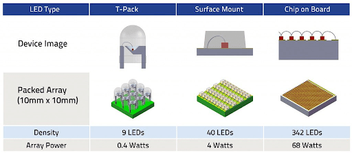
The MCOB types of LEDs that have been recently introduced to the market combine multiple COB LEDs onto a single aluminum plate, generating more than 130 lumen/W.
Another variety, the COB LED flip-chip, is known to have a 70% better heat transmission rate and 30% higher lumen output compared to SMD chips.
3. Printed Circuit Board Core Material
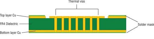
Printed circuit boards host the LEDs (and other electronic components) in a specific arrangement on a flat surface. The role of a PCB’s core material is to redirect the heat away from the components. The most commonly used material is made out of FR-4, a glass-reinforced exposed laminate. Adding thermal vias that penetrate the PCB can significantly improve the thermal resistance.
The second most common core material is ceramic, used mainly for harsh environments characterized by high pressure, temperature, and frequency. Though not as economical as the standard FR-4 type PCBs, they are the better choice in terms of the conductivity of the material used (copper or silver palladium).
The last type of PCB is the metal core printed circuit board (MCPCB), which has either aluminum, copper, or steel alloy-based core material. Copper and aluminum provide superior thermal conductivity and are 6-10 times as thermally conductive as FR4, as illustrated below.
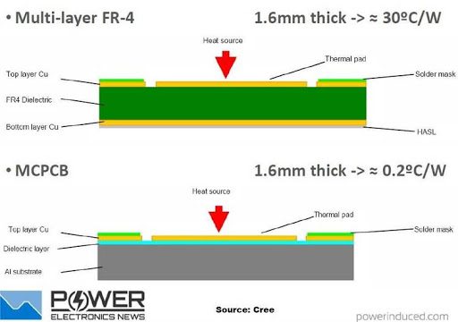
PCBs are one of the most sensitive elements of thermal design given their prime location in the heat pat. Designers must, therefore, be thoughtful when selecting their components. MCPCB may seem like an obvious choice for better heat transfer, however, an FR-4 core PCB with adequately installed thermal vias offers a strong alternative. More research (1) (2) exists on the different types of PCBs and their thermal performances. A complete list of the available PCB technology for LED applications can be found here.
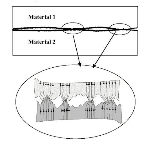
4. Contact Surfaces and Thermal Interface
Heat is transferred from one component to another via surface contact meaning these points of contact must be considered in the overall thermal design process.
Regardless of the means of fabrication, any manufactured part can contain imperfect surfaces, with wavy and rough profiles. When two surfaces are placed in contact, there is normally only a small area of direct physical contact at the interface. And, heat transfer occurs only at these small areas of surface contact.
Reduction in the points of physical contact reduces the heat conduction across the interface, as there will be gaps filled with air, which has low thermal conductivity. Such irregularities and gaps create thermal contact resistance. It is therefore essential to produce contact surfaces as planar, smooth, and clean as possible.
There are two main steps to reduce this thermal contact resistance. The first is to eliminate air by introducing a fluidic material, such as thermal grease, adhesives, phase-change materials (PCM), and filled polymers, into the voids created by uneven surfaces. Thermal grease, for example, can lower the thermal resistance of the interface by a factor of around five (depending on the pressure applied) (3). If a smaller heat resistance is required, the third-party material can be a thermal interface material (TIM) containing fillers that enhance the conduction process. The layer thickness of a thermal interface compound has a significant effect on thermal resistance.
5. Heat Sink Design
Heat sinks play an essential part in managing LED heat dissipation. They are designed to conduct the heat away from the LED and PCB and convect and radiate heat to the surrounding environment. The ambient air circulates through and around the heatsink to help cool it.
The heat sink must transfer the heat away from the PCB so that no thermal buildup occurs within the LED packages. This happens when heat transfer rates of the heat sink to the air outpace the heat transfer rates from the LED to the PCB. The material used to maximize the heat transfer between the PCB and exposed convective surface must be highly conductive, like aluminum alloy which boasts a thermal conductivity of around 190 W/mk.
Radiation does not typically play a major role in the heat dissipation of low-to-mid power LED fixtures, as it pertains mostly to large surface areas and temperatures of over 100 degrees Celsius. However, for high-power LED fixtures (e.g. a high bay light), radiative heat dissipation can become a solution to improve thermal performance. Indeed, such luminaries employ large heat sinks and operate at a high case temperature. Such devices are often equipped with heat sinks that have received some surface treatment like chemical blacking or oxidizing in order to increase the emissivity.
Recent research and projects for natural design heat sinks use computational fluids dynamics and additive manufacturing to produce topology-optimized heat sink geometries.
6. Active Cooling: Small Fans or Liquid Cooling
The air circulating around a heat sink can be either pushed or pulled through mechanical means or with ventilation.
When developing heat sink designs, engineers must consider many constraints such as space, fixture shape, manufacturability, cost, and air conditions. As previously mentioned, convection is a very important factor for the heat management of the whole LED fixture. A passive cooling approach, in which no forces to enhance air circulation are artificially induced, is always favored as it translates to cheaper, quieter, and more reliable designs. Generally, passive cooling designs that rely on natural convection are effective in their role of transferring heat to the air. For some industrial, heavy-duty applications using large power ratings, the heat transfer coefficient must be increased by using a fan or liquid cooling methods.
As an example, a heat sink operating with natural convection would transfer heat to the air at a rate of 5 to 20 W/m2K whereas the use of a fan can increase these values to 25-250W/m2K. When LED fixtures are cooled by liquids, the convection coefficient reaches up to 100-20K W/m2K.
To evaluate these convective heat transfer coefficients at the design stage of the LED fixture, it is very helpful to perform CFD thermal simulations which take into account the 3D geometry, the material, and the environmental conditions and considers all the heat transfer mechanisms to highlight problematic areas in the design. Evaluating the results, engineers can easily discover hot spots and address the issues, using an iterative design process to find a satisfactory solution.
With such an inexpensive, fast, and easy-to-use solution, it is possible to drastically reduce the number of workflow steps over a physical prototype by having already reduced the number of design options through numerical simulations. Furthermore, the capacity of parallel computation, data storage, and reliability that cloud computing offers, in turn, unfolds possibilities for optimizing designs to an extent that has never been seen before.
Conclusion
The heat dissipation performance of LED fixtures depends on a number of factors, materials, interfaces, geometries, and environmental conditions. Taking into account such factors is essential to keep the LEDs cool under working conditions which will therefore prolong their lifetime and satisfy performance requirements. Using CFD thermal simulation numerically replicates working conditions, materials, and heat thermal transfer on a 3D model so that the design engineers can make informed decisions. The time and effort required for many iterative physical tests can be significantly decreased by harvesting the power of CFD thermal simulation in the cloud. Multiple scenarios and designs can be tested simultaneously to rapidly find a thermally effective LED fixture solution. Designing optimized LED lighting solutions can mean a more accessible market price, making energy-efficient LED lighting systems the go-to standard.
Additional Resources on LED Lighting From SimScale:
- On-Demand Webinar: This Might Get Hot! Thermal Simulation of High-Power Density Electronics
- Assessing LED Performance and Eco-Friendly Lighting Options
- LED Cooling: Liquid Cooling Thermal Management
- Electronics Cooling Project: LED Spotlight