In 2017, the global consumer electronics market alone was valued at around USD 1,172 billion, with the LED market taking 50 million of this market share, and in 2024 is expected to climb to approximately USD 1,787 billion. With the increasing demand for high performing, reliable, and quickly produced systems, the complexity and dimensions of embedded electronics are being pushed to higher technical limits than ever before, while electronic applications expand to new domains and industries.
The main challenge is to keep every electronic component within the operational limits set by the manufacturers, in order to guarantee a reliable and safe operation of the system. These operational limits can be of different forms, mechanical stress, fatigue, humidity, vibration, and thermal. The latter is the one which will be discussed in this article.
The Main Problem with this Application: Overheating
Thermal management is one of the most critical tasks when designing electronic systems and it is paramount that the designer integrates the prediction of critical temperatures as a part of the design lifecycle of their product. Accurately predicting temperatures distribution used to be considered an unattainable goal when dealing with complex and detailed models. These values could therefore only be partially evaluated thanks to built prototypes and full-scale experiments, worse case scenario estimation, and approximated design rules.

In this context, the development of computational fluid dynamics (CFD) and conjugate heat transfer (CHT) simulation for thermal management came as an alternative tool that would bring faster, more reliable, and accurate performance prediction. In addition to producing heat maps and temperature distribution plots, engineering simulation would give useful insights into whether a component’s junction temperature under operating conditions ensures high optical LED performance and sufficient lifetime. The results offered by numerical simulation allow designers to predict part and junction temperatures before any manufacturing has taken place.
How to Solve this Problem: Electronics Cooling Systems
In order to limit the temperature rise of electronic components, engineers need to keep them within the correct operating conditions and prevent overheating scenarios. Certain cooling strategies can be deployed by the designer, and the most commonly used are:
- Air-cooled by natural (also known as passive) or forced convection.
- Liquid-cooled through flow circulation of fluid with a pump through a piping system.
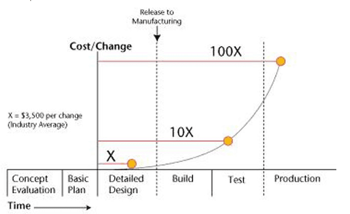
Being able to predict performance, evaluate certain design scenarios, and assess all working conditions before prototyping is of crucial benefit for any manufacturing company. This is particularly relevant for mass production and large series, where the material reduction and manufacturing costs are paramount. In fact, the cost of changing the design further in the production process increases the cost greatly in an upward trajectory, as shown below.
An undetected overheated component of a product that goes to market could result in a product recall to minimize potential dangers. We’ve seen this recently at the release of Samsung’s Galaxy Note 7 phone, where only after the device was brought to market it was discovered the battery could become overheated causing the phones to explode in some cases. The phones have since been recalled.
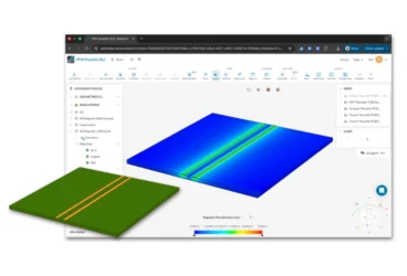
In the following case, we will demonstrate how engineers can evaluate products in the design phase from a 3D CAD model to accurately validate performance. Using CFD, users can experience great advantages over traditional methods including saving time, money, and obtaining deeper insights.
Our Case: Conjugate Heat Transfer (CHT) of an LED Spotlight
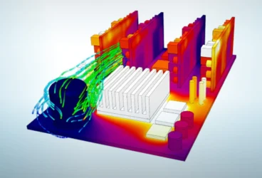
LED spotlight cooling is a suitable example where CFD can be used for optimizing a design in order to predict temperature distribution and therefore avoid components overheating. This overheating could result in catastrophic damage and failure to the whole system, adversely impacting not only the normal operation of the system but to a larger extent, the safety of human operators.
The model that is to be analyzed is a standard LED spotlight generating 9W of thermal dissipation power, these spotlights are fairly common in households and provide an energy-efficient solution as a lighting apparatus. The overall goal of the simulation is to verify that the heating elements of the LED spotlight design have their temperature kept under the 90°C/363.15 K operational limit. The results will provide an evaluation of the dissipation performance of the components of the LED light under natural/passive cooling conditions.
Simulation Setup
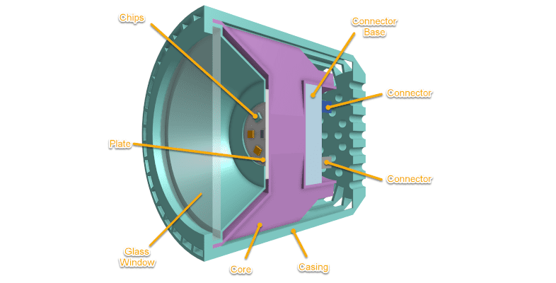
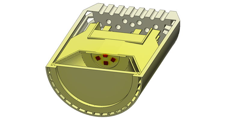
The setup starts with the import of the LED light’s CAD model, representing the most significant details of the geometry that will affect the flow distribution and the temperature profile of the device. The CAD model consists of a casing, a glass protector, a metal core, a supporting plate where the chips are placed, as well as electrical connector parts. For simplicity, only half of the whole model is used for this project and a symmetrical condition is assumed throughout. A rectangular volume enclosing this LED light model represents the air domain, this enclosure is created on the platform, once the geometry is imported.
This project is a conjugate heat transfer analysis, which solves both the conduction and convection heat transfer phenomenon. This way, the distribution of the temperature through the heat sink and the other solid components will be computed taking into account the convection from the airflow. Since this is a natural convection situation, the airflow is driven by the buoyancy effect generated by the heated surfaces.
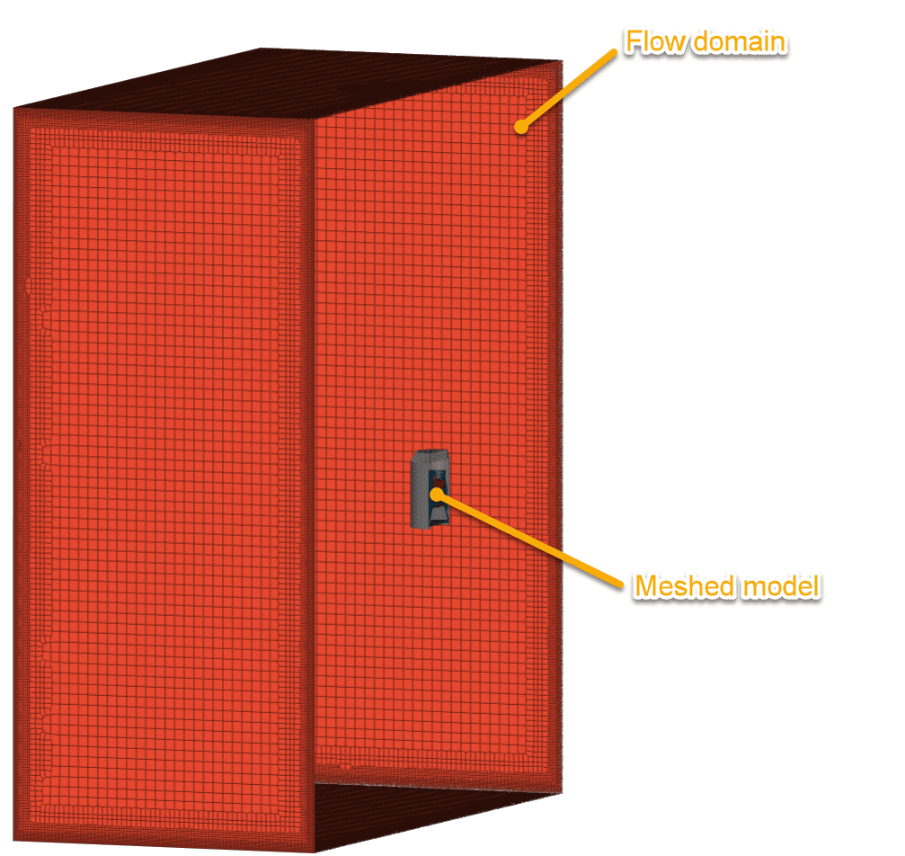
Once this analysis is selected, the first step is to generate the mesh. Meshing is an operation that aims at generating simple basic elemental volumes of the different parts of the CAD model. These parts—which represent both solid and fluid volumes—are broken down into small elements where fluid governing equations will be computed by the solver. The mesh is defined with elements small enough to ensure that the geometry has been captured to a relevant level of detail and that the mesh density is high enough to accurately capture the flow and solid distribution of temperature, velocity, and other quantities.
Material Assignment
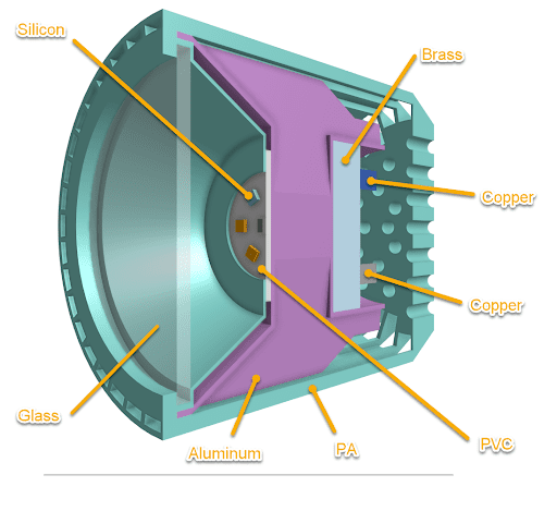
Benefiting from the parallel cloud computing, the rest of the simulation can be set up while the mesh is being generated. After the gravity is defined with the LED spotlight facing down, materials for the fluid and solid volumes can be defined. The casing is made out of PA material and the core made out of aluminum.
Boundary Conditions
With this simulation representing a LED spotlight in an open environment, the faces of the air volume are set as open boundary conditions, meaning that the air is free to go in or out of the domain. Since the simulation is simplified to half of the actual LED light model, the symmetry faces of both the fluid and solid parts are set to symmetrical boundary conditions.
The heating sources are assigned to the volumes that represent the LED chips made out of silicon, where three are assigned a power of 2W, and the one in the middle is set to 1W since it is cut in half by the symmetry plane.
Results
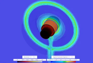
The solver is set up for 1000 iterations, and the top face of the 2W and 1W chips are set for monitoring the temperature as goes through these iterations, confirming when numerical convergence is reached. The temperature distribution on the solid part shows how well the heat is transferred from the heating element to the rest of the geometry.
A few observations can be made here. First, the heating chips have their temperature kept at 345 K, below the operational limit of 363.15 K; on average, 30 degrees higher than the PVC plate that they are attached too. This demonstrates the importance of the thermal interface between the chip and the board, which can sometimes be enhanced by applying some thermal paste. Second, the temperature over the rest of the components is quite homogeneous and kept within a reasonable range, i.e., lower than 300 degrees Kelvin/26 degrees Celsius, which is a temperature that allows bare hands handling.
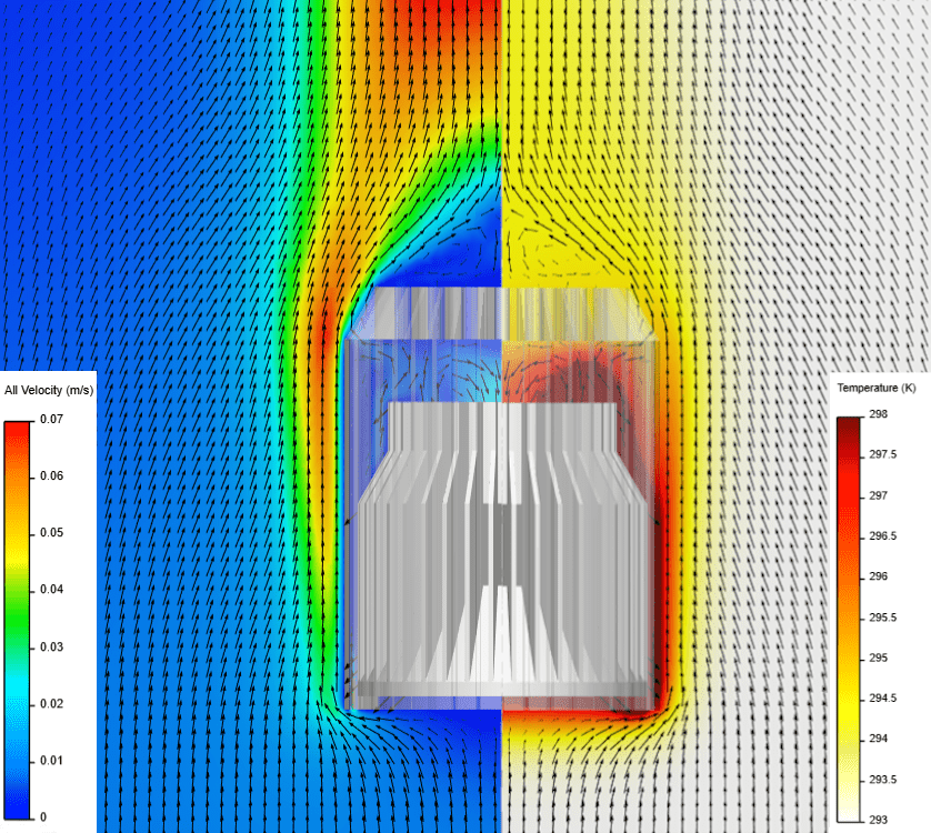
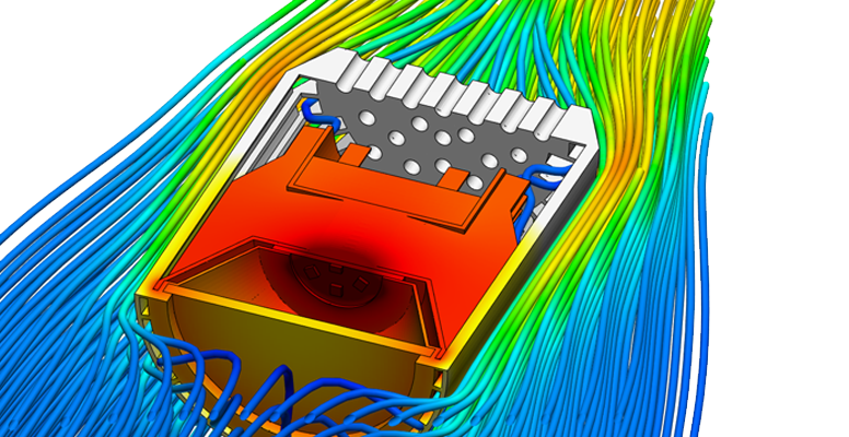
The velocity profile as the air flows along the length of the LED lights shows the velocity ramping up as it catches heat from the higher temperature surfaces. Convective induction is formed at the extremity of the vertical surface, this effect is characterized by air streams joining behind the LED spotlight. This generates some recirculation zones at the upper face of the PA casing. The casing being hollow at its rear, some recirculation and stagnation zones can be denoted in this region, which results in heat being higher in this zone.
Conclusion
The goal of this electronics cooling project was to predict the temperature at the heating chips and heat distribution performance on the components of an LED spotlight. The CHT simulation was used to evaluate the flow and heat pattern of the specific design with specific material properties, geometry, and size, ultimately assessing the LED performance. The initial setup process was described for a specific load case and environment. The results highlighted the importance of the thermal interfaces between the different components in terms of heat dissipation, as well as the conductivity of materials in place. The fluid flow was then described to highlight some characteristic phenomenon of buoyancy-driven air flows present in natural convection electronic cooling case.
The results showed the surface temperature of 345 K at the heating chips which proves that the design was satisfactory in order to maintain the component within their operational limits of 363.15 K. This design could be further improved by, for example, improving the board conductivity by using thermal vias or increase its copper content.
Additional Electronics Cooling Resources from SimScale:
- White Paper: The Ultimate Electronics Cooling Guide
- 5 Ready-To-Use Electronics Cooling Simulation Templates
- How to Use CFD Analysis for Electronics Cooling
- Thermal Design Optimization for Better Electronics Cooling
- Testing the Cooling Performance of a Heat Sink for Different LED Packages