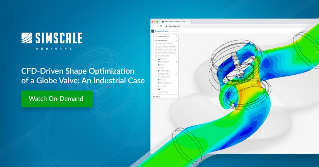
An increasingly competitive global market for manufactured components demands a very high level of performance in modern engineering products that must use optimization to meet requirements. The parameterization of a globe valve geometry for robust and flexible shape variation is a complex process that has been simplified and automated. Gemü, a leading global manufacturer of industrial and specialist valves, is constantly researching novel methods to improve its valves’ performance and develop their forever more niche applications. Their in-house engineering team relies on simulation and optimization tools to help deliver the best-in-class valves to its customers across multiple industries. Gemu provided a globe valve to shape optimize using the workflow from SimScale to CAESES®. The CAD geometry is imported into SimScale and meshed automatically. A flow simulation is run with a 1 bar pressure drop through the valve with hundreds of design experiments (DOE) runs using the shape optimization tool CAESES from Friendship Systems. The simulation runtime is in minutes, and all simulations are run in parallel using the practically unlimited computing power of the cloud, leading to design insights that significantly improve overall valve performance.
Flow Simulation to Shape Optimization
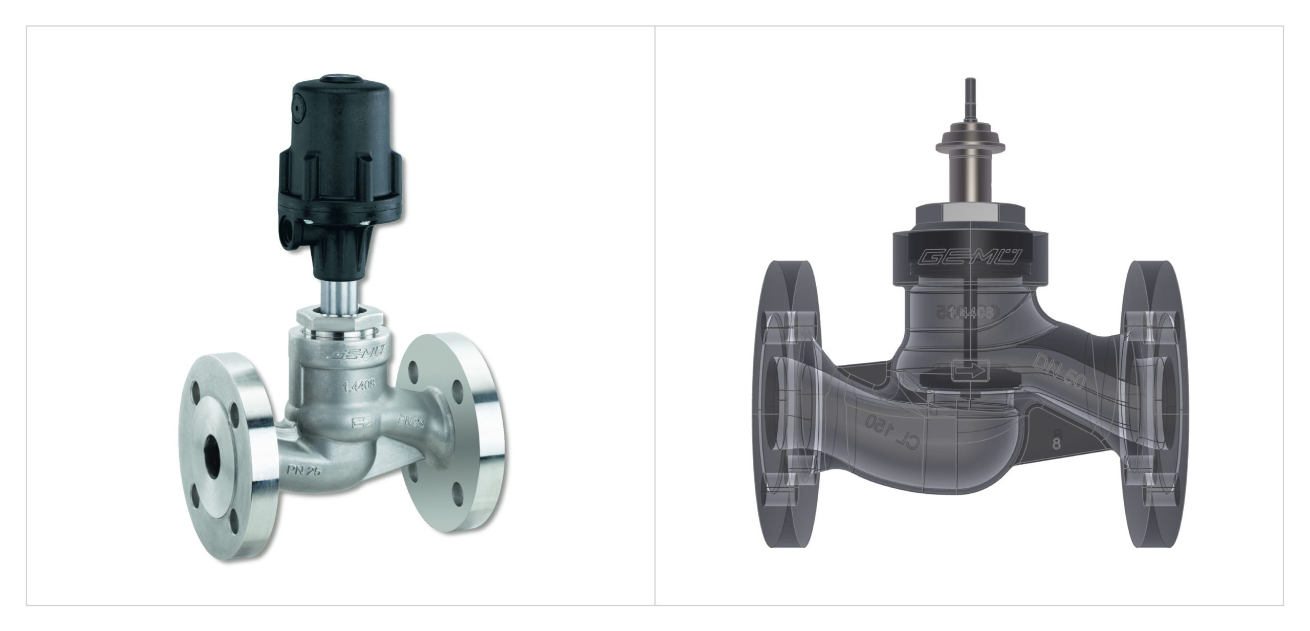
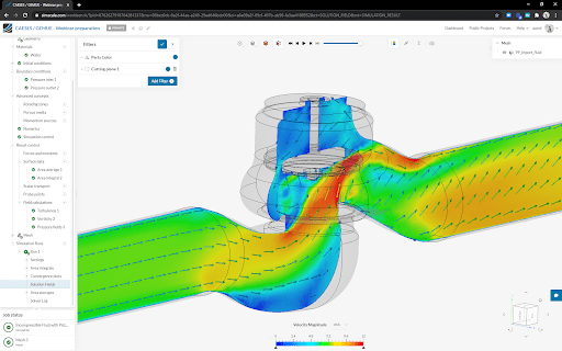
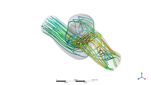
A GEMÜ 534 globe valve is used for shape optimization, as shown in the image below. The valve exhibits a sharp change of flow direction resulting in higher pressure loss and lower flow rate values compared to a more common angle seat valve body. This valve has a pneumatically operated plastic piston actuator and is available as a shut-off or control valve. The valve is standard in industrial water treatment applications, chemical processing, power plant operations, and mechanical and processing industries. A conventional CAD tool has limitations for optimization, especially for complex geometries where small changes in shape can disproportionately influence outputs such as flow and pressure. Because of these highly sensitive relationships between design change input and performance output, the physical processes governing valve performance are complex and challenging to quantify. The non-orthogonal geometry of the valves also means that many geometric input variables influence their performance. This study aims to investigate the relationship between geometric inputs and valve performance using numerical methods and identify any potential for cost and development time savings.
Most typical bottlenecks in setting up and running a design exploration or optimization process are related to the handling of geometry, as these specialist requirements are less common in the engineering discipline. Geometry variation with traditional CAD systems is often tedious or prone to failure, and it is challenging to consider or even automatically fulfill constraints. Simulation engineers depend on CAD teams to provide geometry (variants) based on manual or ad-hoc simulation analysis. The quality of the CAD model might also not be suitable for simulation (e.g. water tightness, level of detail), which is another common hindrance to spending some time setting up an optimization study. The CAESES tool can be used to overcome these common issues and using the CAESES/SimScale workflow, a simple workflow for this case has been developed as follows:
- Choose a suitable baseline CAD model that is suitable for simulation
- Parameterize the CAD model using CAESES
- Define boundary conditions and simulation setup for the CFD analysis (SimScale)
- Identify the design/parameter space (DoE) that needs to be solved (CAESES)
- Run CFD simulations on selected CAD variants (SimScale)
- Analyze results
- Reduce the number of CAD variants
- Optimize (CAESES)
The basic simulation setup is a 1 bar pressure inlet with water as the fluid. The outlet pressure is ambient. In this case, fluid flow rates, temperatures, or material properties were not altered, although this would be a simple enough exercise using the parametric simulation features in SimScale. CAD variations using several key geometric dimensions are the focus of this study, and the valve geometry has 16 parameters that have been parameterized using the CAESES tool. The inlet and outlet fluid domains have been extended on either side to allow a developed flow to enter the valve.
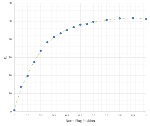
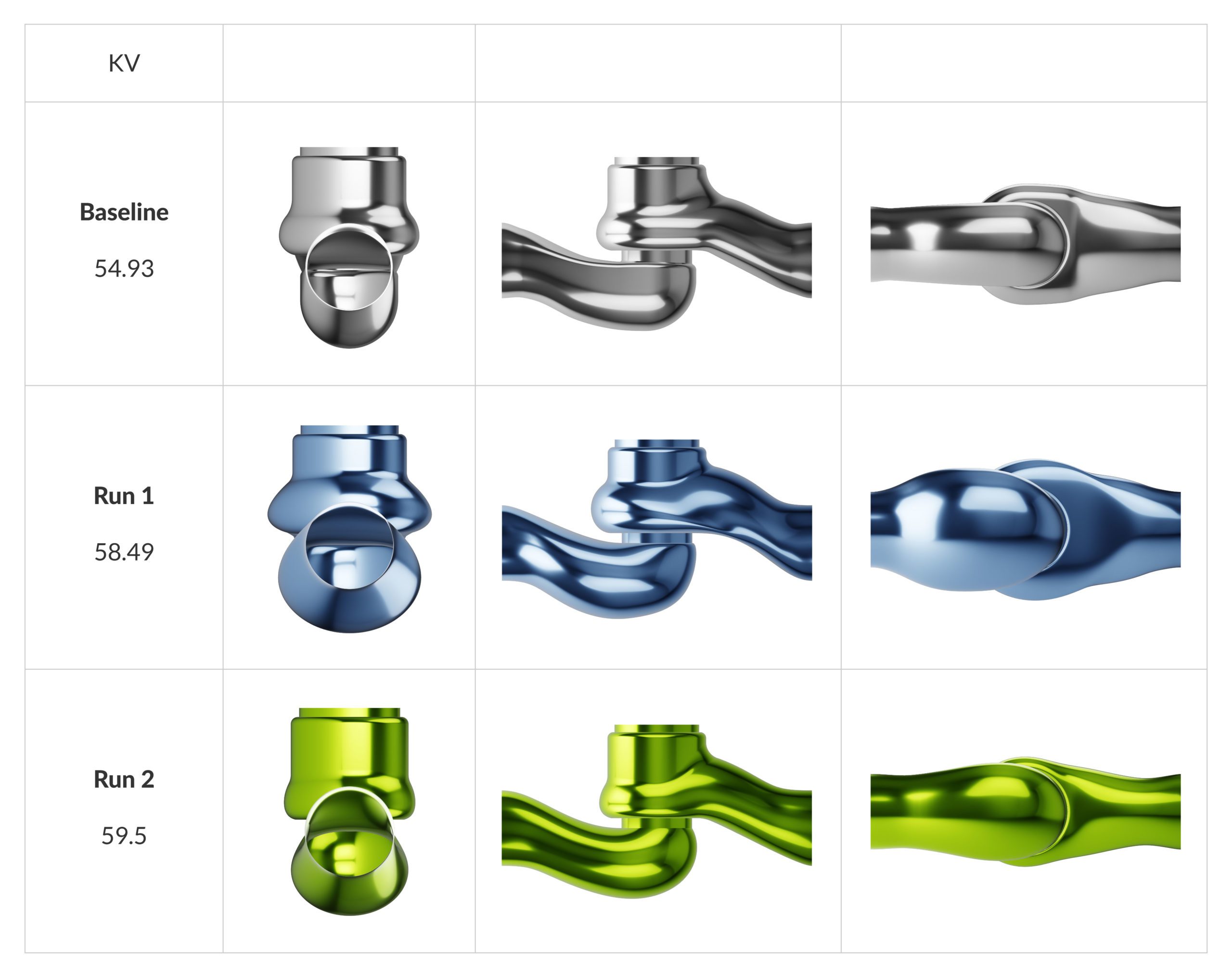
In this case, we are looking for significant improvement in the Kv value for the globe valve, a standard measure of valve capacity. The Kv value expresses the amount of flow through a valve at a given valve position with a pressure loss of 1 bar. The unique situation when the valve is fully open is referred to as the Kvs value. When the plug is closed, the flow is zero, and it increases with plug opening in a correlation that depends on the type of valve. This study aims to improve upon the Kv value for this particular globe valve using geometry optimization.
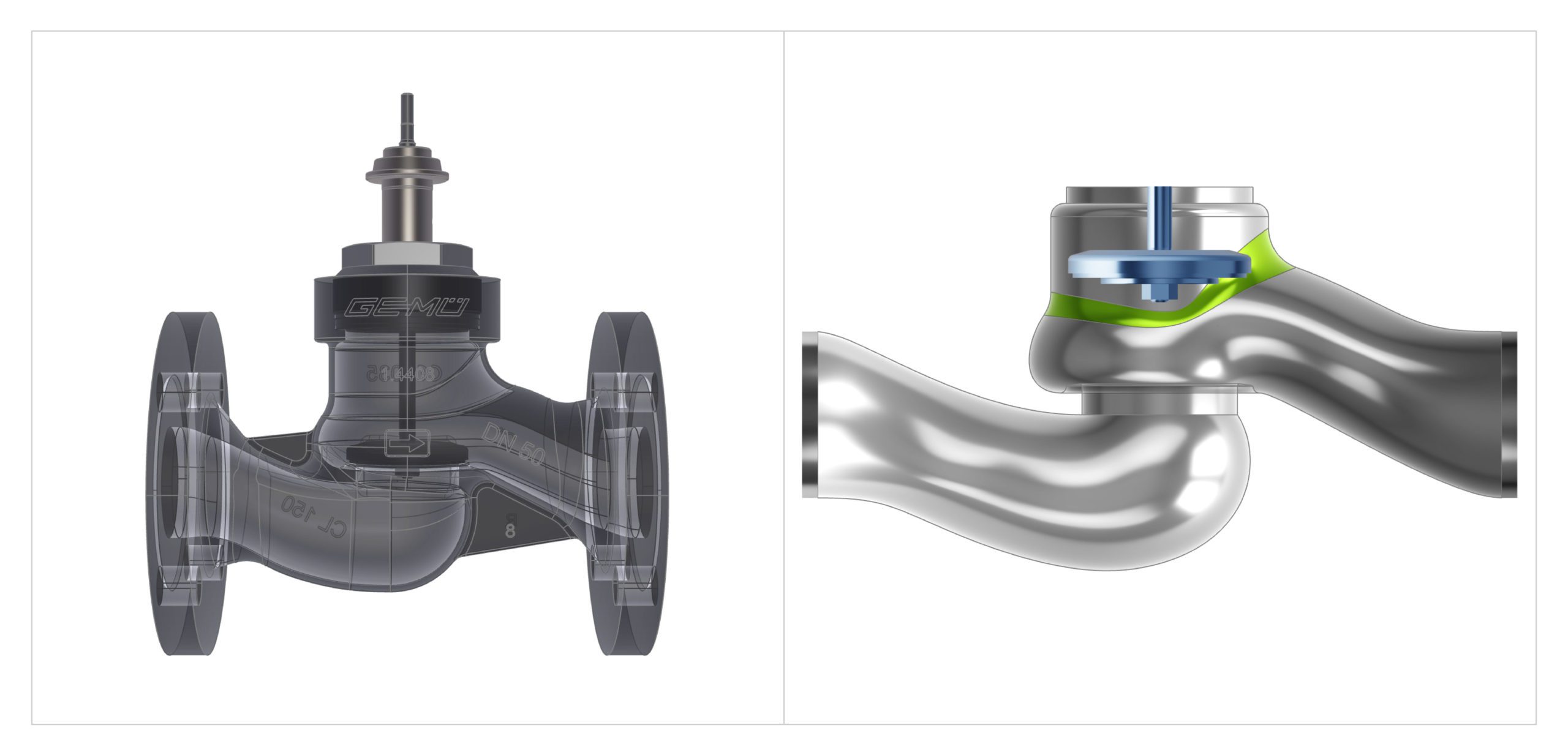
The geometric dimensions are referred to as contours on the CAD model. The following images show two of these contours using a simple line diagram and how changes in those contours affect the 3D CAD model or extracted fluid domain in this case:
- Inlet and Outlet
- 4 parameters on inlet long contour
- 2 parameters on inlet short contour
- 4 parameters on outlet long contour
- 2 parameters on outlet short contour
- Cross-sections:
- 2 parameters for inlet ellipse aspect ratio distribution
- 2 parameters for outlet ellipse aspect ratio distribution
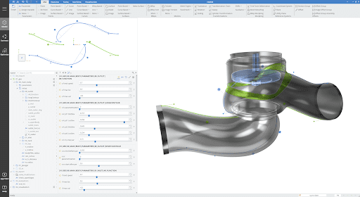
Once CAD preparation and parameterization are done, the model in CAESES can be connected to SimScale using the API and instructed using a Python script. At this point, the parameterized model, which has a generic interface for coupling to external analysis tools, could also be used for different types of physics analysis, including structural and thermal analysis. Defining input and output parameters is also done at this stage to allow simple interpretation of results, which is needed when the extraction of result values is used as objectives or constraints by the optimization algorithm. Geometry and script files are exported from CAESES and loaded into the SimScale platform. The result files generated from SimScale are downloaded to the local workstation after the simulation for further analysis (CAESES runs locally). Using the parameterized geometric contours, the initial design of the experiment starts with 120 designs or shape candidates. In this optimization case, cycling through the first optimization iterations of the workflow, the 120 designs are followed by a response surface optimization and reduced to 50 designs. The baseline Kv of 54.93 has now increased to 58.49, an increase of 6.5%.
The original 16 parameters have been reduced to eight, and two additional parameters have been added for the long contours and two cross-sections, now giving 12 parameters for the second run. This has been based on flow simulation results (Flow rate and pressure drop to determine the Kv value). Further simulations and optimization led to an increased Kv value of 59.5, an 8.3% improvement over the baseline.
Simulation-Driven Shape Optimize Globe Valve
Computational fluid dynamics (CFD), combined with shape optimization, is a powerful tool for engineers and designers who want to optimize their product designs. SimScale can be easily connected with specialist third-party tools using the SimScale application programming interface (API).
Simulation can increase knowledge about a product’s behavior early in the design process and offer insights for improvement, along with quantitative and visual evidence critical in making informed decisions. Simulation-driven Shape Optimization and automated design exploration amplify the benefits of simulation further leading to better product designs with vastly reduced design cycles.
The critical components of this ideal tool-set are a simulation tool, a driver of the optimization process with suitable DoE and optimization algorithms, and finally, an appropriate CAD tool that can produce different geometry variants based on the feedback from simulation results. This workflow has been used to improve the Kv value of an industrial globe valve by 8.3%.
Follow along step-by-step in this on-demand webinar that shows how leading companies in the fields of CFD-driven shape optimization are using SimScale to automate their design process: