Electronic components are complex in design, with many small parts, made out of many different materials. This complex design contributes to how the component performs thermally. For this reason, it can be difficult to predict the junction temperature in order to ensure the component does not overheat or fail. Computational Fluid Dynamics (CFD) is commonly used to thermally test the design of electronics to ensure that individual component temperatures do not exceed their limits. However performing a CFD analysis on a detailed model, incorporating all the materials and parts, can be complex, expensive, and often not necessary.

For electronics products such as printed circuit boards (PCB), packaging or flip chips, carrying out thermal analysis using a detailed model would require a complicated simulation setup. The meshing process alone of a detailed model demands time and computational power. In response to this challenge, thermal resistance network models can be used instead to simplify the process.
What Is Thermal Resistance?
Recognizing the need for faster analysis in the competitive electronics market, many engineers benefit from making the switch from detailed component modeling to thermal resistance network models. Thermal resistance network models cut down the design challenges and computational time, thereby shortening design cycles for design optimization. Performing CFD analysis on this type of model allows an engineer to obtain reliable results while keeping the simulation simple.
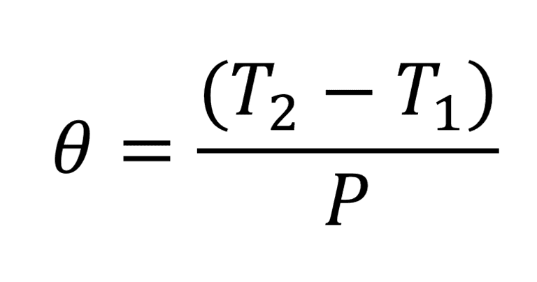
Thermal resistance is the ratio of the temperature difference between two points divided by power. As an example, a plank of wood can be used to demonstrate resistance. The temperature on the one side of the wood minus the temperature after it has passed through the wooden plank is divided by the amount of power, thus providing the thermal resistance. If only one temperature and power is known, then we can also calculate the remaining temperature.
Our Case: Thermal Modelling Comparison
In a detailed SimScale webinar, the use of thermal network models was explored. A thermal resistance model uses resistances to obtain temperature at the junction, which is where failure can be best estimated. The model can also provide case temperature, board temperature (the interface between the component and the board), and the sides of the case. These resistances can help form an estimate of the junction temperature. The junction is the core of the heating component, usually the die or equivalent.
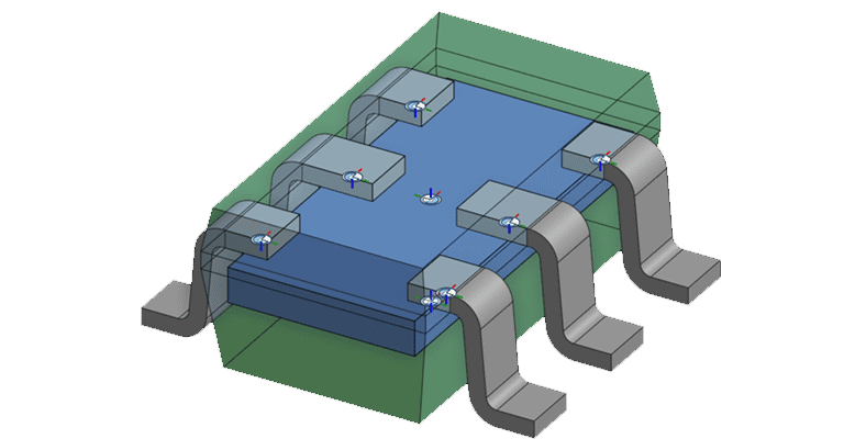
A thermal resistance network model can be defined in SimScale as an advanced concept. For a component to act as a thermal resistance network, the top face of the component is selected and the directional resistance is applied. Board and case resistance are generally provided by the manufacturer of the parts or can be obtained from physical tests or a detailed model virtually tested with CFD. The power is defined in the same way as in a detailed model.
The geometry used for a thermal resistance model must be accurate in terms of dimensions and area. A cross-section of each face should be the same as a detailed model. It is required to keep the shape simple such as a cuboid.
Download our ‘Electronics Cooling Guide’ now for a complete overview!

Thermal Resistance Model vs. Detailed Model
Setup: Defining the Models
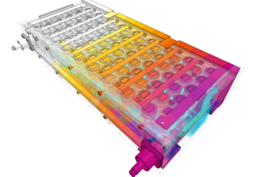
This simulation project was a comparison of a resistance model against a detailed model. Starting with the detailed model, all details are included in the design. The full list of materials was applied for the detailed model, including silicon, plastics and aluminium. The test environment is set up to include important standards defined by the JEDEC board. The dimensions and materials in this simulation are typical for tests done in aims of meeting these standards.
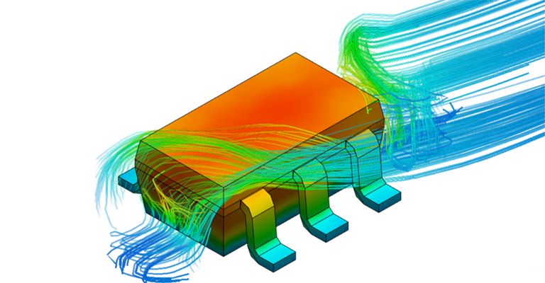
The conjugative heat transfer type is selected to address the thermal effects involving both fluid and solid components. A probe point at the center of the die is selected and assigned into the simulation to monitor the temperature convergence and to read the junction temperature. Many companies choose to define a thermal couple as a probe to record ambient temperature, to enable calculation of the junction to ambient resistance which is useful for analytical calculations. So this has also been included for demonstration. Contacts are automatically defined in this simulation type, so there is no need to include touching areas manually. Solid and Fluid (air) properties are defined and gravity is set according to the geometry. The simulation is then run and the results analyzed.
Results of the Thermal Modelling Comparison
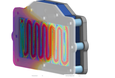
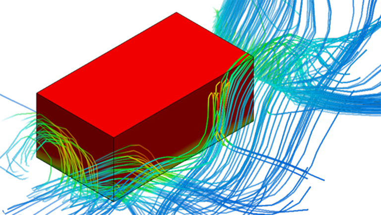
Results from the average temperature at the probe point on the die can be used in combination with average surface temperatures for the top, bottom and sides to generate a thermal resistance network model which is then defined in SimScale in the advanced concept node in the simulation setup. This can be applied to the simplified geometry that does not contain all the material properties and details for faster and simpler analysis of the component’s design.
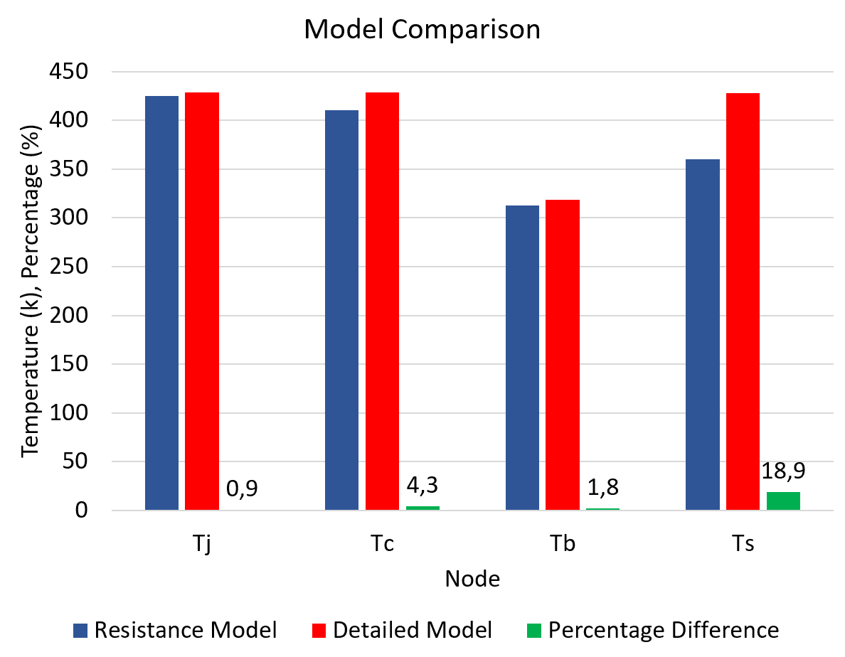
When the comparison between both models is made, the junction temperature is remarkably close. Just one percent difference can be seen between the two models, showing a highly accurate corroboration of the thermal resistance model against the detailed model. In fact, all other temperatures at various points in the model show good agreement, suggesting that airflow surrounding the component is also accurately represented using the thermal resistance model. A larger difference can be seen in the side temperatures, where the measurement method and complexities caused by the leads used have created a difference of just under 20%.
When comparing the streamlines and surface temperatures, the simulation shows the sides to give an average value which can be used to find the junction temperature. Where a detailed model is better suited to comparing surface temperatures against results from technology such as thermal imaging, a thermal resistance model provides speed, robustness, and accuracy for junction temperature analysis.
Conclusion
Overall, using thermal resistance network models gave accurate and reliable results that nearly always depicted a close estimate to the temperatures concluded in tests made using the detailed model. From these conclusions, thermal resistance models are shown to be a much faster way to produce useful estimations of thermal resistance, temperature distribution, temperature variation, and other thermal characteristics in electronic components.
Don’t forget to explore our social media pages to stay up to date on the latest from SimScale and CAE trends. Find us on LinkedIn, Facebook, and Twitter.