Should you use conventional mixing ventilation or design a displacement ventilation system for your building? Buildings come in all shapes and sizes, and most are designed with more than one purpose in mind. In order to create a healthy and productive environment, you, as the designer, must select the air distribution system that best meets the building’s goals. Throughout the design process, you will be presented with a variety of potential options and configurations, all differing in terms of cost, thermal comfort, and energy consumption. So how can you accurately and efficiently evaluate your options and avoid iterative and time-consuming changes during the later phases?
The answer lies in computational fluid dynamics (CFD). To illustrate how CFD simulations can help you identify the best air distribution system, we carried out a comparative study of mixing and displacement ventilation systems in a small office space during a short webinar on December 19th, 2017. Watch the recording for free!

Why is Simulation Important?
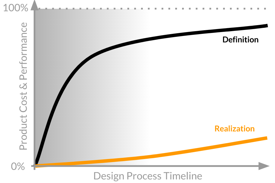
The cost and performance of any physical product are typically determined quite early in the design process. The stage when you begin to explore the design space and define your product concept is when the most impactful design decisions are made. After that, the rate at which the production costs are realized is much slower.
Simulation is one of the tools that play a fundamental role in those early product development stages, allowing engineers to make more informed design decisions earlier in the process. For the final product, this can mean lower production costs, more efficient energy consumption, lower failure risk, and more.
Why SimScale?
Why aren’t all designers using simulation yet? Several barriers have prevented a more widespread adoption of simulation software by engineers and designers—and here’s how SimScale is aiming to challenge this status quo:
- Accessibility: Traditional software needs to be installed locally on expensive high-performing computers, most of which remain idle most of the time. With SimScale, all computations are cloud-based—all that is needed is a web browser.
-
Operating costs: Standard commercial simulation software packages are notoriously expensive. With SimScale, there is an option to start simulating right away with a free Community Plan.
-
Know-how: Most modern tools are designed for experts and experienced simulation engineers. To bridge that knowledge gap, SimScale offers a large public projects library, free training, and live support chat.
Displacement Ventilation The Engineering Problem: Evaluating Ventilation Designs
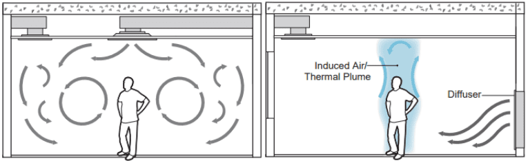
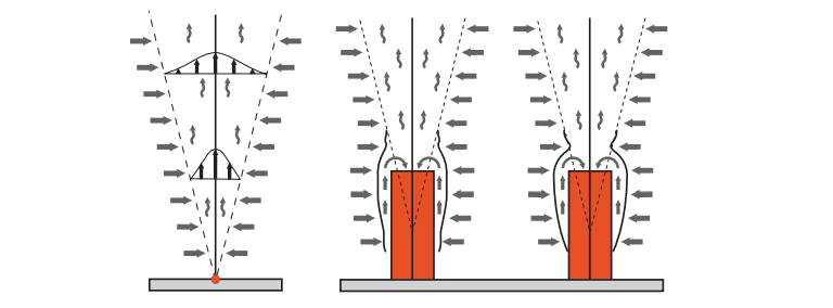
In contrast with traditional mixing ventilation (MV) systems, a displacement ventilation system (DV) is an air-distribution strategy that introduces conditioned outdoor air at a low velocity from air supply diffusers usually located near floor level. The cool air accelerates because of the buoyancy force, pooling near the floor level, and is then carried up into the thermal plumes that are formed by heat sources (e.g., occupants, electric appliances). The air is consolidated at the ceiling level for extraction and doesn’t re-enter the occupied space. This type of air-distribution strategy can effectively deliver fresh air to occupants and remove the contaminants associated with heat sources, creating a comfortable and healthy environment as a result.
The DV technology has been a standard practice in the HVAC industry in Europe over the past decades and has also gained popularity in the US where it is frequently applied to classroom and office spaces.
Displacement Ventilation: Pros and Cons
Choosing the best ventilation system design can be a difficult decision because each approach has its own unique strengths and weaknesses. Multiple factors need to be considered, including indoor air quality, comfort, energy consumption, and cost. Supplying air from diffusers located near floor level has significant design implications. The air must be supplied at higher temperatures and lower velocities to avoid uncomfortable drafts. Therefore, the air diffusers need to be much larger than those of other air distribution systems. The air diffuser size is an important consideration since it must be accommodated within the building design. At the same time, delivering air at a lower velocity allows fans to run more slowly, lowering energy consumption and producing less noise. If the building layout accommodates the size and other special requirements of a displacement ventilation system, it can be a healthy and energy-efficient option that is highly suitable for offices, educational facilities, and other large open spaces.
To sum up the benefits and limitations of a displacement ventilation system compared to conventional mixing ventilation:
Benefits
- Improved indoor air quality
- Better acoustics and less noise (applying displacement ventilation diffusers rather than mixing-ventilation diffusers can reduce sound levels by an NC factor of 5)
- Lower pressure drops, smaller fans, and lower energy consumption
- Fewer diffusers and less ductwork necessary
- Higher ventilation effectiveness (free cooling may be available most of the year)
Limitations
- Cannot be applied as widely
- More complex supply air ducting
- The diffusers are more expensive
- The neutral room temperature is higher
Displacement Ventilation Design Optimization Study Using CFD
Analytical methods and small-scale laboratory experiments are sometimes used for predicting natural ventilation flow features in buildings. In the design stage, these techniques are useful for understanding the flow characteristics, including the likely ventilation rate, any thermal stratification, and fresh air distribution. As an alternative, computational fluid dynamics (CFD) is being increasingly employed for predicting building airflows and testing natural ventilation strategies. With the recent advances in computing power, the process of creating a CFD model and analyzing the results has become much less labor-intensive, thus reducing the time and the associated costs. CFD has the advantage over analytical and experimental methods of providing airspeed and temperature data at many locations throughout the flow field.
Download this free case study to learn how the SimScale cloud-based CFD platform was used to investigate a ducting system and optimize its performance.

Project Overview
The following project was used for the purpose of this study: Displacement Ventilation CFD Analysis. The aim of this project is to evaluate the air-conditioning performance of a partitioned room under two typical ventilation modes: (1) mixing ventilation, and (2) displacement ventilation system.
For a total of six representative air-conditioning scenarios, CFD simulations are performed to examine temperature distribution and local thermal comfort for two partitioned spaces. Simulation results indicate that temperature distribution in a partitioned room is a strong function of the ventilation strategy (mixing vs. displacement ventilation) but is marginally affected by diffuser arrangements.
Simulation Parameters
-
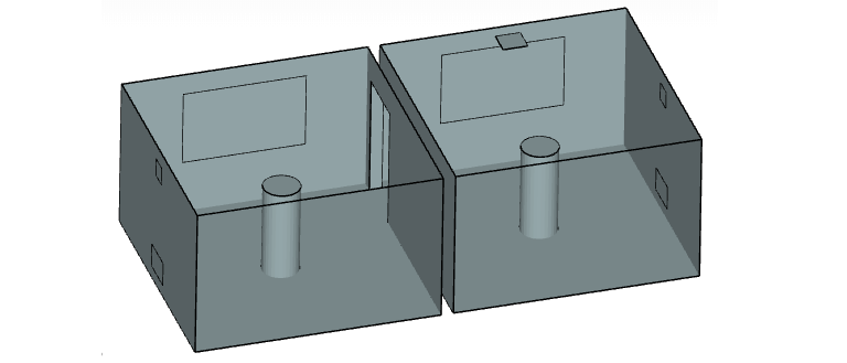
The computational domain that consists of the two identical spaces with a dimension of 4 m × 4 m × 2.5 m. The two spaces are connected by a door in a partition wall, and the air can move from one space to the other.
-
Each space has a 2 m × 1.25 m window and a cylindrical human simulator with a height of 1.5 m and a radius of 0.3 m.
-
A wall supply diffuser is located in each space at ceiling height for the mixing ventilation case, whereas the supply diffuser is at the floor level for the displacement ventilation case. In both cases, the exhaust is located at the ceiling in only space B.
-
This simple setup provides a test case for two most relevant real-world scenarios:
(1) partitioned spaces served by only one diffuser—probably because partitioning of indoor space has been carried out after the building design phase, and
(2) each partitioned space is served by one diffuser as originally designed. A total of six simulation scenarios considering two ventilation strategies (mixing vs. displacement ventilation) and three diffuser arrangements are examined. -
For boundary conditions, the supply diffuser and the exhaust were modeled as a velocity inlet and a pressure outlet, respectively. The inlet velocity varied from 0.135 to 0.74 m/s in order to supply the constant ventilation airflow rate of 3 h−1. The supply air temperatures were 16°C for the mixing ventilation and 19°C for the displacement ventilation system.
-
To mainly concentrate on the effects of the room airflows on indoor thermal condition, outdoor conditions were excluded by making the envelope of the model adiabatic, with the exception of windows and the human simulators. The window emits 400 W (160 W/m2) sensible heat flux and the human simulator emits 70 W/m2 of total heat flux, which represents a seated person doing standard office work such as typing or filing.
-
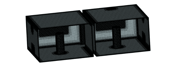
Among the two possible equation turbulence models, the shear stress transport (SST) k–ω turbulence model was employed because of its performance in predicting turbulent indoor airflow associated with thermal plume and wall-bounded flows in indoor environments.
Displacement Ventilation Simulation Results
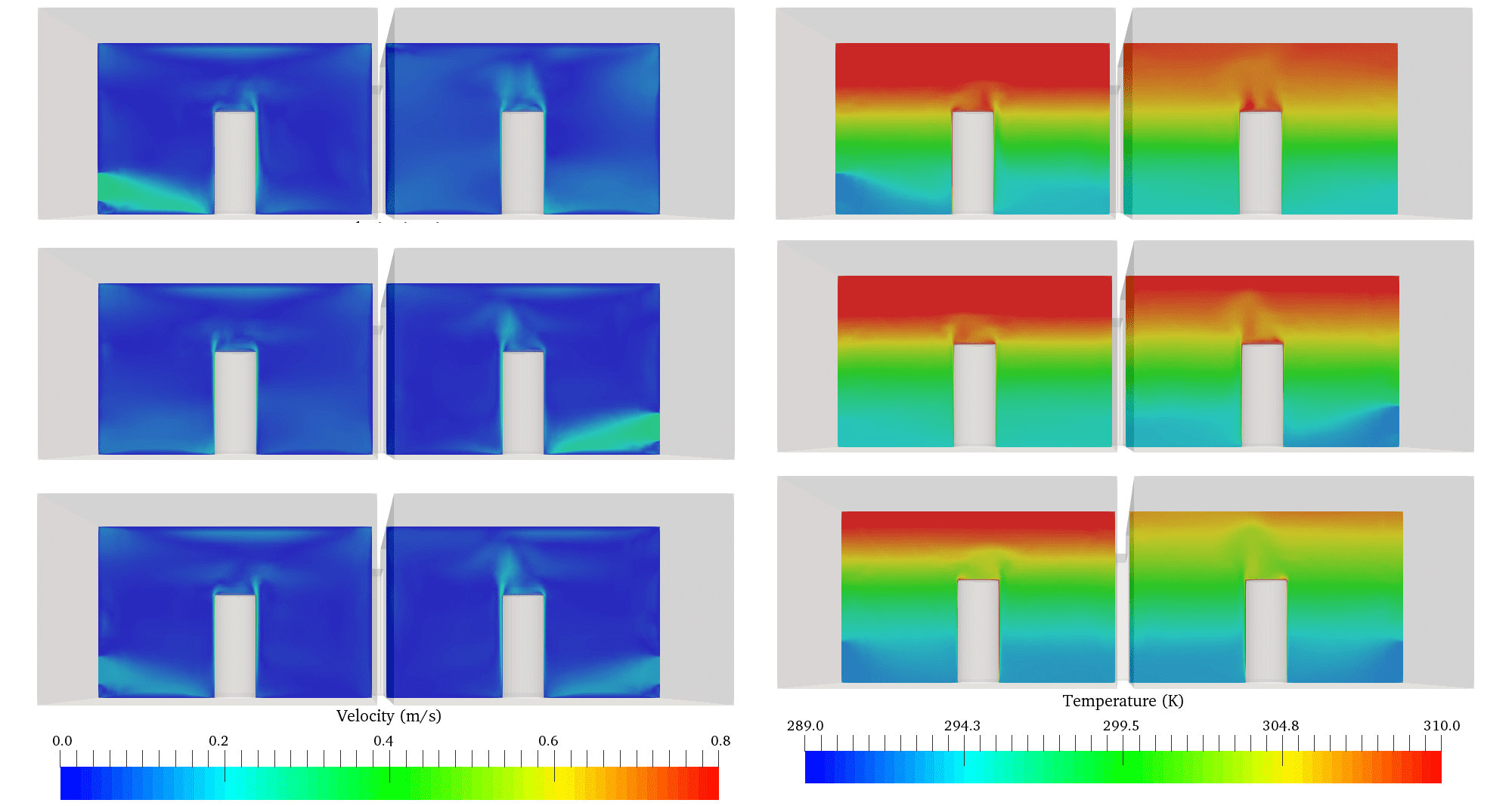
Temperature and velocity distribution under the three displacement-ventilation systems scenario
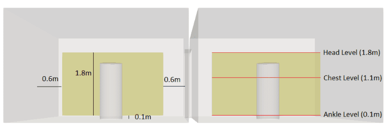
For the displacement-ventilation scenarios, temperature stratification in the breathing zone is apparent. Temperature ranges from 18°C to 30.3°C in the breathing zone with higher temperatures with increased heights. This pattern occurs because cool air supplied from the floor-level moves upward as the supplied air is heated by indoor heat sources. Despite different arrangements of diffusers, simulation results of the displacement ventilation system show that the average temperature in the breathing zone is 18 – 20.6°C. Temperature above the breathing zone reaches 30°C for the space with the exhaust, while it exceeds 35°C for the space without the exhaust.
For the displacement ventilation, however, the head-level temperature is higher than desired. This might be the limitation of the displacement-ventilation system when limiting the airflow rate as a controlled parameter.
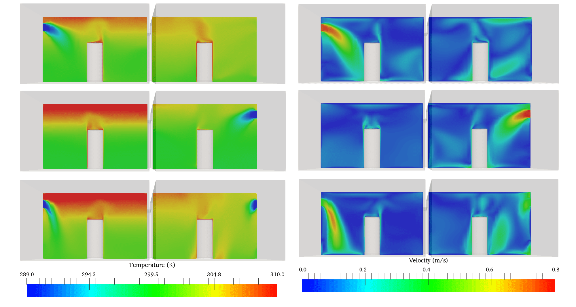
For mixed ventilation scenarios, the average temperature in the breathing zone (0.1 m to 1.8 m above the floor) of the partitioned spaces is 19 – 21.3°C. This air pattern in the breathing zone is consistent regardless of the diffuser arrangement, although the temperature is not perfectly mixed above the breathing zone of the space A where no exhaust is available.
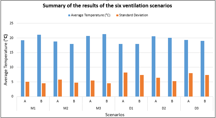
Higher standard deviation of average temperatures is apparent for the displacement ventilation system as compared to the mixing-ventilation system. This is due to the thermal stratification, which is absent in the mixing-ventilation system. The overall average temperatures for both the systems are approximately the same and fall in the comfortable temperature range in the breathing zone.
Local Discomfort
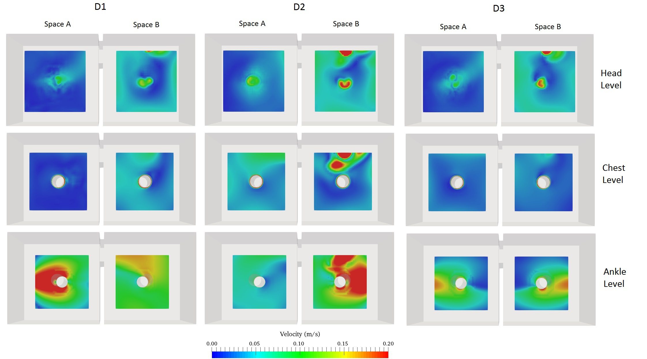
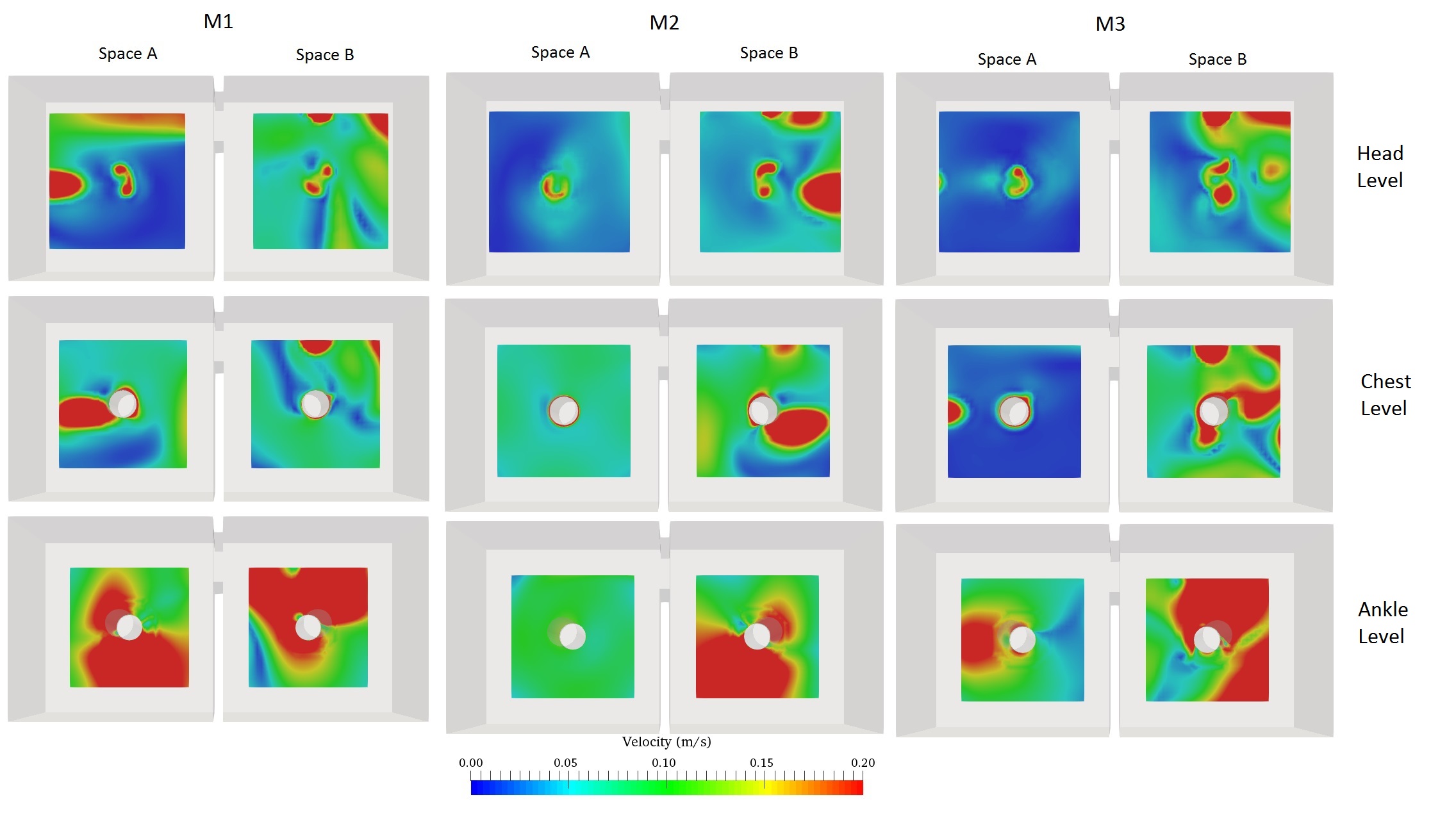
In the figures above, the red-colored area represents the region with the velocity magnitude > 0.20 m/s where occupants may experience local draft due to the high airspeed and the operative temperature is lower than 22.5°C.
The two figures above illustrate that in the mixed ventilation scenarios, the local draft is considerably higher in comparison with the displacement ventilation scenarios. Also, in the displacement ventilation system, airspeed is notably higher and the air temperature is as low as 18.2°C at the ankle level, so local discomfort could occur near the ankle level. Airspeed greater than 0.2 m/s is frequently found at the ankle level when only one diffuser is operating.
When both diffusers are working at low speed, the local thermal discomfort is significantly reduced on the ankle-level plane. Increasing supply air temperature can be an alternative that prevents local thermal discomfort at the ankle level while reducing energy consumption.
Displacement Ventilation Conclusion
This is just one example of how CFD tools can help HVAC engineers predict the performance of their designs and optimize them accordingly. The SimScale Public Projects Library has a wide selection of free simulation templates covering various design aspects of HVAC equipment optimization, energy efficiency, cooling and heating, thermal comfort, commercial and industrial fan design, contamination control and clean room design, wind engineering, and many more.
Explore them by creating a free Community account. Watch the free webinar to learn more:
References
- https://www.sciencedirect.com/science/article/pii/S0360132315301189
- https://www.irbnet.de/daten/iconda/CIB6113.pdf
- www.inive.org/members_area/medias/pdf/Inive\IBPSA\BS05_0381_388.pdf