Computational science is the use of computers to solve complex problems. Computational science has the potential to solve complicated problems in very cost-effective ways, and as a result, it is becoming more and more popular in the scientific world. Additionally, as computers are becoming more advanced and powerful, the resulting simulations are getting better and better. In fact, the future of all scientific experimentation and engineering analysis lies with computation and simulation. Computational science is now widely accepted as the third pillar of scientific research, complementing both experimentation and theory.
Computational fluid dynamics (CFD) is the major branch of computational science, and it refers to the use of computers to solve fluid mechanics problems. If you’re new to CFD, our complete guide to CFD analysis covers the fundamentals and core principles. In CFD software, Navier–Stokes equations are solved at different points on the grid by using different numerical methods and schemes.
The CFD Workflow:
Every CFD problem has the same workflow which can be divided into three basic steps.
- Pre-processing
- Processing
- Post-processing
1. Pre-Processing
Pre-processing in the CFD software workflow involves the preparation of geometry, meshing the geometry, setting up the material properties, initial and boundary conditions.
Geometry Issues
Having a good CAD geometry—one without defects—is crucial for the setup of a CFD analysis. Common geometry defects are:
- Missing faces

- Overlapping faces
- Gaps
- Free faces, edges, nodes
- Sharp angles
Preparing the Geometry
- Fill the gaps
- Split surfaces with high curvature
- Remove unnecessary details
At the end of the preparation stage, the geometry should be a clean, watertight solid. It can be uploaded in different formats such as .stp/.step, .stl, .iges or .brep, but the recommended one is .stp/.step because it is more stable than other formats.
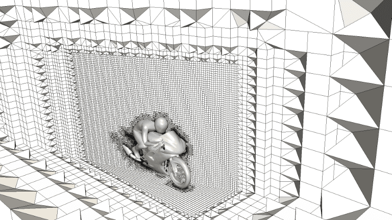
Mesh Generation
Mesh generation is a crucial step in the CFD workflow. It divides the physical domain into a finite number of discrete regions called control volumes or cells. The numerical solution is calculated in these individual cells by solving the governing fluid flow equations inside. How the mesh should be refined depends on the specific problem. For example, care must be taken to ensure that areas with large changes in fluid properties are adequately refined. In this respect, the physics of the problem helps. Make an intuitive guess of the flow profile and then refine the areas of the large gradients. Always start with a coarse mesh and then gradually refine the mesh for the specific areas. Keep the mesh size as small as possible within accuracy limits.
Selection of Mode and Flow Properties
The simulation model is selected based on the physics of the problem. The first step is to select the simulation type (incompressible, compressible, natural convection, etc.). Once the simulation type is selected, set the other physical problem parameters. For example, if you want to calculate the effects of turbulence on the fluid flow, set turbulence as a parameter, or, in contrast, set it to laminar if you want to neglect the effects of turbulence on the fluid flow. If the fluid flow is time-dependent, you can choose the transient setting and if you need a solution that is independent of time, selecting the steady-state option would be best.
Specification of Initial and Boundary Conditions
Now we have to provide the material properties, initial conditions, and boundary conditions. Assign the material properties to the fluid. One of the most important parts of setting up a numerical simulation is giving initial and boundary conditions. Numerical simulations are based on solving the partial differential equations on the given domain, and these equations require the initial and boundary conditions—depending on the problem type—to be well-posed.
2. Processing
The next step is specifying the numerical parameters, i.e setting up solver parameters, discretization schemes, etc. Depending on the simulation type, every problem has its own unique structure. Usually, one problem can be solved by multiples solvers and with different solver parameters; however, to efficiently solve the problem, it is very important to give the correct solver parameters and numerical schemes.
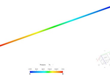
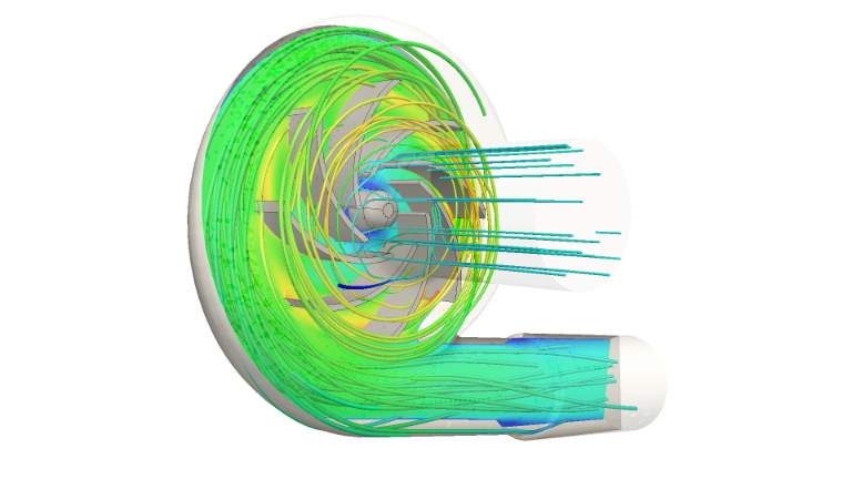
3. Post-Processing
One of the major parts of any numerical simulation is interpreting the results. This is done in post-processing. The flow fields are analyzed by different filters like streamlines, contour plots, etc. Post-processing is the final step in the CFD workflow, and it allows you to visualize your simulation results and make decisions for design optimization.
Here it is, a quick guide to get you through your CFD software analysis. Follow these steps to set up your simulation and get the results you want. And if you need more in-depth explanations, here are a few articles worth reading: How to Set Up Boundary Conditions in Your Simulation?, Step-by-Step Tutorial: Water Flow Through a Gate Valve, Best CAD Software: How to Choose It?
Download this case study for free to learn how the SimScale platform was used to investigate a ducting system and optimize its performance.