
Spearpoint Engineering Relies on Cloud-Based Simulation from SimScale

26 total simulations

Average simulation time of 20 minutes
26 total simulations
Average simulation time of 20 minutes
Spearpoint Engineering is a service driven consulting company that specializes in mechanical and structural work across various sectors such as mining, oil and gas, agriculture, construction, public and municipality.
When Mr. Elias Zwane Pr.Eng., principal engineer at Spearpoint Engineering, undertook a new project to offer a design for upgraded wet spent grain silos to replace existing silos that have reached the end of their 20-year life cycle at SAB Brewery in South Africa, it was clear that computer-aided design would be a must-have tool in his design workflow.
SAB Brewery used the silos to store wet spent grain in their operation. Ideally, these silos would have been fabricated from stainless steel or have been lined inside to prevent corrosion from the water. However, the cost to fabricate the silos from this grade of steel was a limitation, and thus the silos needed to be upgraded to compensate for this and improve the overall longevity of the superstructures.
Instead of stainless steel, the silos are fabricated from structural steel, S355JR Grade. Without coating, this grade of steel corrodes when in contact with water. Coating of the internal surfaces of the silos alone is not an effective strategy, because of the traction caused by the flowing material. Corrosion ruins the integrity of the steel structure.
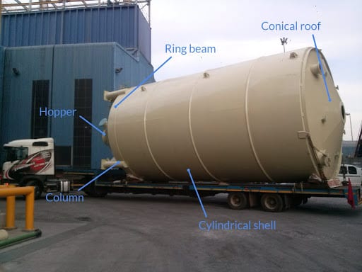
A typical silo structure consists of a cylindrical shell, a conical roof and hopper, stiffeners, and legs (columns) welded together, as shown in the image below. Longitudinal and transverse butt welds are generally used to join sections of the silo.
As a first step, Spearpoint Engineering worked out the measurement schedule for non-destructive testing (NDT) to measure the thickness on strategic positions of the existing silos. A subcontractor led by Spearpoint was sent on site to perform NDT on the silos. This was necessary to understand the rate of corrosion on the silo during service so to answer the end-user’s strategic question on the life of the newly designed silos.
The characteristics, serviceability and ultimate design loads of the silo were calculated from the relevant standards. The compliance criteria were calculated from the laws and principles of applied mechanics, strength of materials, and relevant standards. This includes design against permanent deformation, elastic stability and fatigue.
To achieve the mission profile for storage and discharge, the new design adopted the shape and size of the existing silos. The computer-aided-design (CAD) of the new silo was then created to later be used for simulation.
The assessment of the new design under different design loads against the compliance criteria for such a structure could not be simply achieved analytically, and experimental approaches turned out to be too costly and lengthy. The use of SimScale as a cloud-based CAE platform became an obvious choice for Elias who, having used other CAE software in the past, discovered the flexibility of working from any computer, not requiring any expensive computer, but still using the advantage of high computational power. He also found the versatility and affordability of such a tool unprecedented in the CAE market.
The CAD model of the newly designed silo was imported into the SimScale platform in a parasolid file format. Mechanical properties, design loads, and boundary conditions were applied to the model. The model was discretized with tetrahedral solid elements. The sensitivity of the results to the mesh size was eliminated through a mesh convergence study.
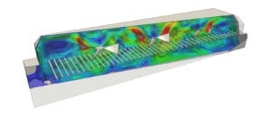
Under ultimate design load, linear static analysis was performed and von Mises stress experienced by the silo was assessed against the 90% of the yield strength of the material to safeguard against permanent deformation. Next, nonlinear static analysis was conducted under the ultimate design load case to assess buckling on the silo. To find out where and how the buckling occurred, the team used force-time graphs that were later made visible in the deformed results of the solutions field.
The buckling analysis revealed that the first mode of buckling to be occurring happened on the bottom segment of the silo. This segment was then suggested to be improved upon by protecting it from corrosion during service. This was the first area cited to be upgraded from the previous design, as the previous design had no internal liners on this segment.
Under serviceability design loads, linear static analysis was performed, and deflections of the silo superstructure were compared with the allowable serviceability limit deflections. The maximum principal stress on the different detail categories of the silo were compared against the constant amplitude fatigue limits of the corresponding detail categories, in order to safeguard against fatigue crack initiation.
The slenderness ratio of the silo superstructure was greater than 4, suggesting that the wind would have both static and dynamic effects on the silo during service. To safeguard the structure against the effects of wind passing over the silo, such as vortex shedding induced vibrations (resonance), the frequency at which vortex shedding occurs around the silo in the area was quantified.
Modal analysis of the silo superstructure indicated an overlap of one of the natural frequencies of the silo with the frequency of the vortex shedding. The mode shape of this frequency was then also analyzed in the SimScale platform. The modal stiffness of the intercepted mode was altered by 20% by adding stiffeners to the superstructure. This was an iterative process achieved by modifying the CAD model, uploading it to SimScale platform, and simulating until the desired results were achieved.
Using the SimScale platform brought me the following motto: When the clients ask if I can perform a particular project, I am fully confident that SimScale is behind me, I have the tools I can rely on, and I am definitely resourceful.

Mr Elias Zwane
Chief Engineer at Spearpoint
Spearpoint engineering was very happy with the outcomes of the non-linear buckling, linear static, and frequency analysis from SimScale. They were able to observe that there was an area of improvement from the existing silo, and were then able to calculate the critical thickness needed for the improved silo design, as well as determine an area where stiffness should be added to alleviate effects of vortex shedding.
All and all, Elias was able to trust the results from SimScale, and put forward the simulation results of his new design. The team at Spearpoint was able to say with great certainty that the specified thickness to replace the silo was accurate, and that their new design which focused on lining only the bottom segment of the shell was indeed an upgrade from the previous silo design.
Subscribe to our newsletter
By subscribing you agree to with our Privacy Policy
Product
Solutions
Resources
Sign up for SimScale
and start simulating now


