As a cloud-native application, SimScale is able to continuously release new features and perform regular product maintenance on the fly. We realize that it’s often difficult to keep up with the latest news so this blog provides you with an opportunity to get up to date with all of the main new features released in Q4 2022. Enjoy!
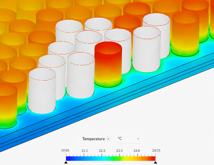
Transient Conjugate Heat Transfer
Transient simulations capture changes over time, where no steady state really exists.
- Components heating or cooling over time
- Fans failing — how long does it take until critical temperatures are reached?
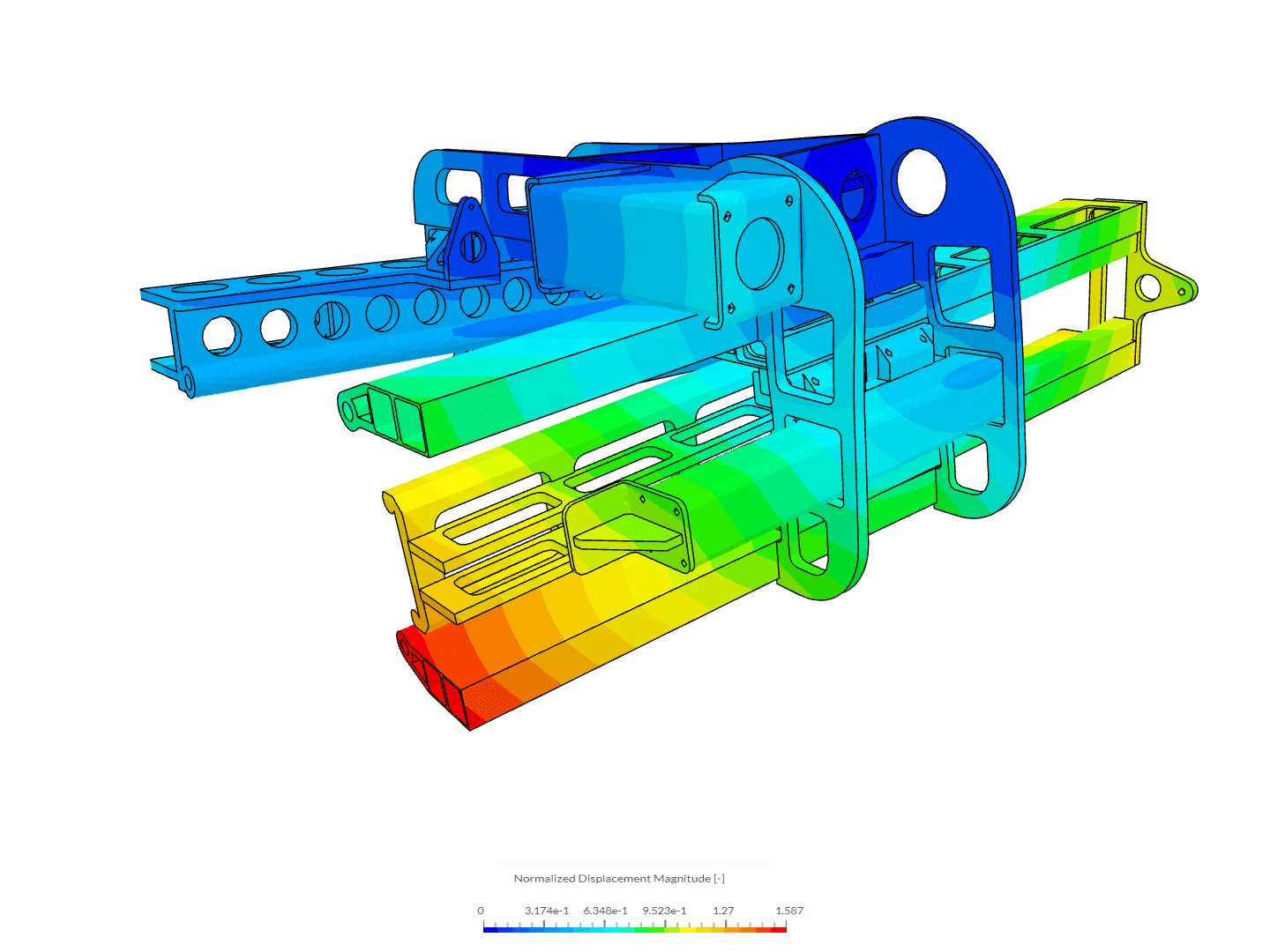
Individual Color Settings for Model Parts
It is now possible to change color settings independently for each part of the simulated model. This improves rendering by allowing users to customize their scene and enhance results visualization over the original model.
Wall Roughness Factor for Multi-Purpose Simulations
It is now possible to add the wall roughness factor for more accurate modeling of wall boundary conditions in Multi-Purpose simulations. For applications such as rotating machinery and flow valves, it is important to model surface roughness in order to accurately assess its influence on flow conditions and calculate pressure rise/drop.
This functionality allows analyzing complex model cases such as:
- Erosion of surfaces due to cavitation or particulate matter
- Accumulation of particles (debris) on the surfaces
- Inherent roughness of the material used
- Manufacturing processes e.g., 3D printing can create uneven surfaces
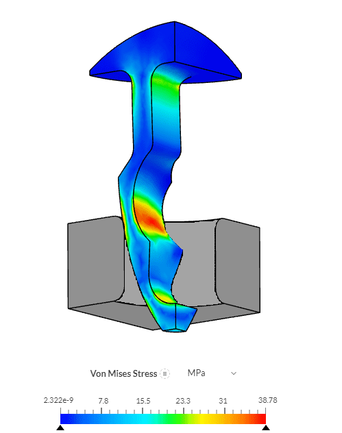
Stress-strain Mapped from Company Material Library into SimScale
It is now possible to directly use a stress-strain curve from your company material library for structural simulations. This means faster simulation setup times and reduced input errors. Users will no longer need to characterize elastoplastic material behavior and nonlinear materials with data tables and can directly utilize the material behavior available in their company library.
The added value of this functionality is especially useful for:
- Analyzing elastoplastic material behavior of mechanical components
- Simulating fasteners where the stress-strain curve is mapped vs temperature
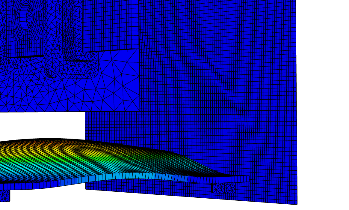
Thin Section Mesh Refinement for Structural Analysis
Maximize accuracy and solution efficiency by modeling low-thickness parts with second-order hexahedral and prismatic elements using the new ‘thin section mesh refinement‘.
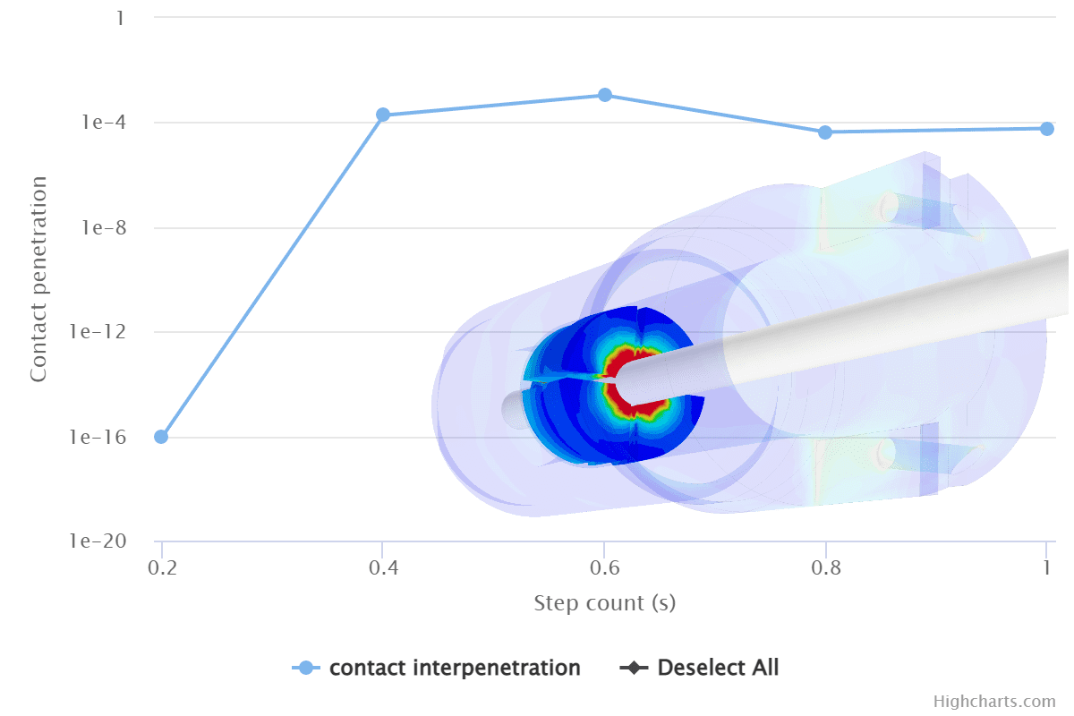
Physical Contact Monitoring
During nonlinear contact simulations, you are now provided with contact monitoring plots keeping you in the loop on contact penetration and solution convergence, giving you confidence and control over your result outputs.
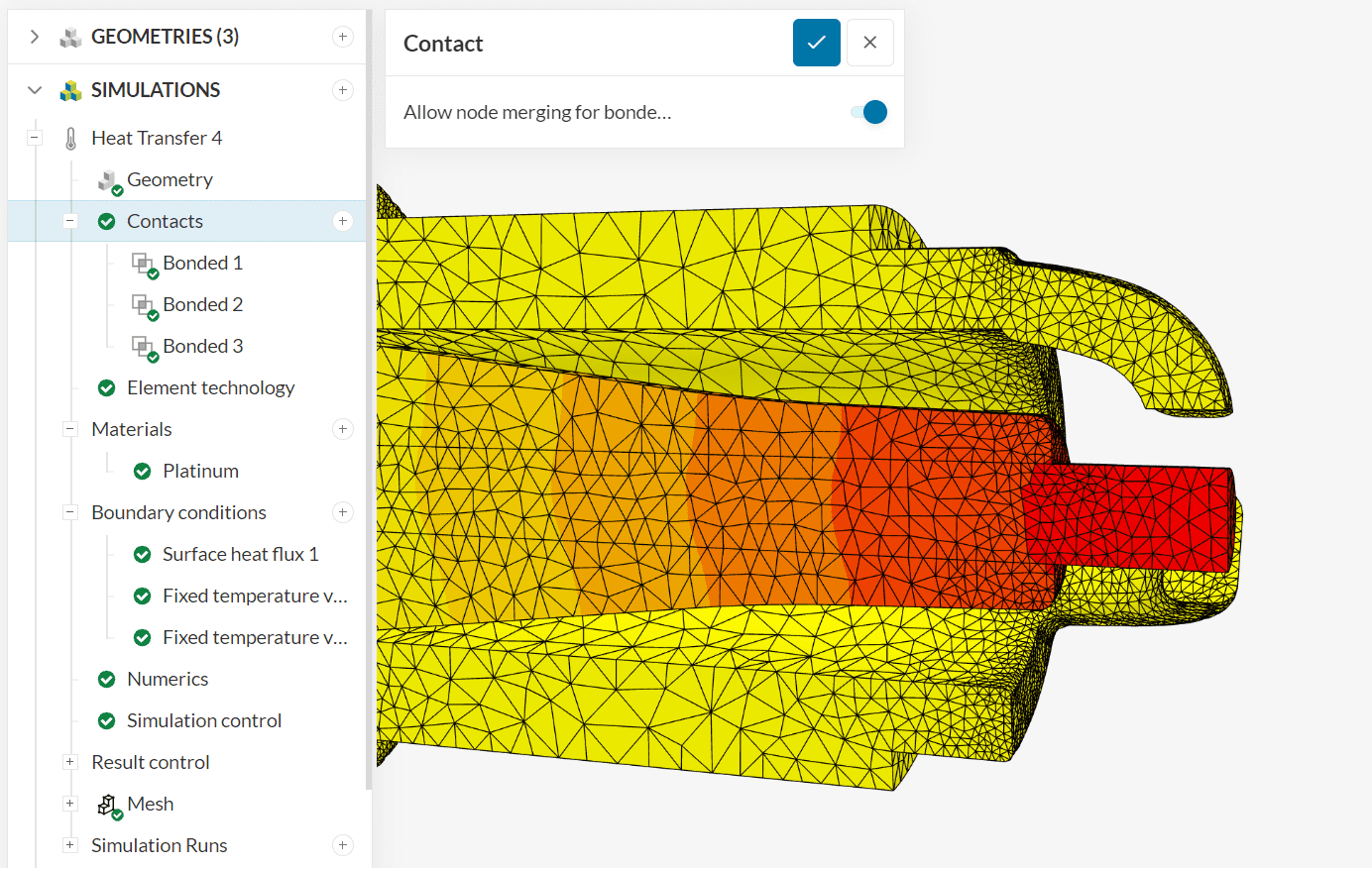
Conformal Meshing for Heat Transfer Analyses
This is the first step in the direction of conformal meshing for all structural analysis which will bring gains in terms of bonded and thermal contact accuracy as well as dramatically improved solution performance thanks to the merging of nodes at contact surfaces.
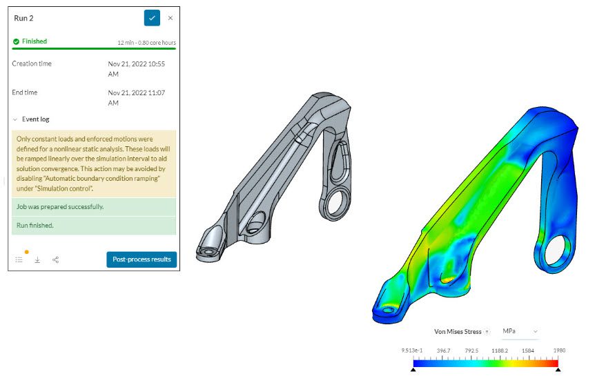
Non-linear Static Analysis Stability: Automatic Boundary Condition Ramping
Increasing the automation and robustness of nonlinear static analyses. This feature will ramp up constant loads in the background if necessary for a stable solution.
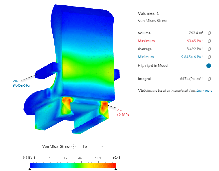
Highlight Minimum and Maximum Values
Highlight the minimum and maximum values for a given result quantity (within Statistics). This is an extremely valuable way for engineers to quickly and precisely view simulation results.
It is especially useful for:
- Locating the maximum stress within a structure to predict the factor of safety
- Identifying the highest displacements within assemblies
Clear Vibration Result Presentation
A number of post-processing improvements have been released to provide intuitive and clear default post-processing for vibration analyses.
- Frequency analysis deformations are now scaled for a perfect fit within the viewer
- Magnitude and phase are now set as default for all result fields in harmonic analysis, providing physically meaningful visualization of complex quantities
- Absolute motion results can now be visualized for harmonic analysis with base excitation allowing direct comparison with physical test data
Improved Robustness for PWC and Incompressible (LBM) via Manual Velocity Scaling
The LBM solver on SimScale used for the Incompressible (LBM) and Pedestrian Wind Comfort analysis, pacefish®, is using an explicit time stepping to solve the transient flow analysis. For some cases where we experience locally very high velocities in automotive aerodynamics or urban wind simulations, the local LBM velocities can surpass the stability cliff of 0.5, leading to divergence. For such cases, we enable an option in the simulation control to manually adjust the velocity scaling factor to a value lower than the default value of 0.1.
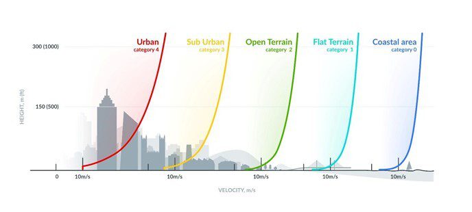
Aerodynamic Roughness in PWC and LBM
This feature provides two new input options for Aerodynamic Roughness:
- Enable the direct definition of “Aerodynamic Roughness”, e.g., z0= 0.5m to represent a Suburban exposure or z0 = 1m for an Urban Exposure
- Alternatively, using an automatic definition “from Exposure”. Here the selected surfaces will get the respective aerodynamic roughness from the exposure category for each individual wind direction assigned
Natural Convection Boundary Condition for Natural Ventilation Cases
Connect outdoor wind simulations with internal, natural convection studies. The natural convection boundary condition takes into account the facade pressure conditions influenced by outdoor wind and surrounding buildings, improving the accuracy of indoor CFD analyses.
The workflow for the natural ventilation boundary condition consists of the following steps:
- Run a Pedestrian Wind Comfort (PWC) study on the building of interest and its surroundings
- Apply the facade pressure results from the previous simulation as reference pressure for the natural ventilation BC in a consecutive indoor analysis
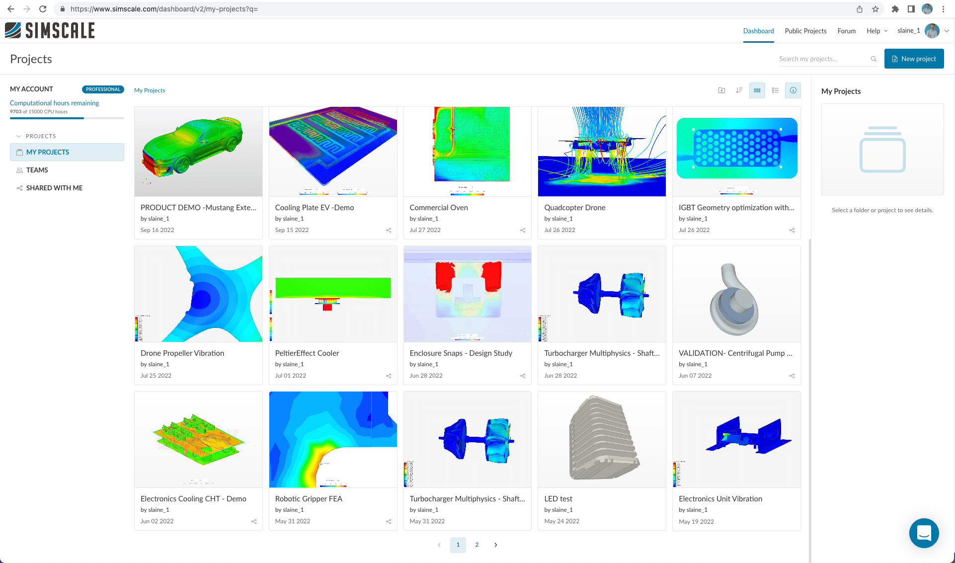
Dashboard Folders and Spaces
- You can now organize your projects into folders
- Companies can also create spaces that give access to limited groups of users
Take These New Features for a Spin Yourself
All of these new features are now live on SimScale. They are really just one browser window away from you! If you wish to try out these new features for yourself and don’t already have a SimScale account then you can easily sign up here for a trial. Please stay tuned for our next quarterly product update.


