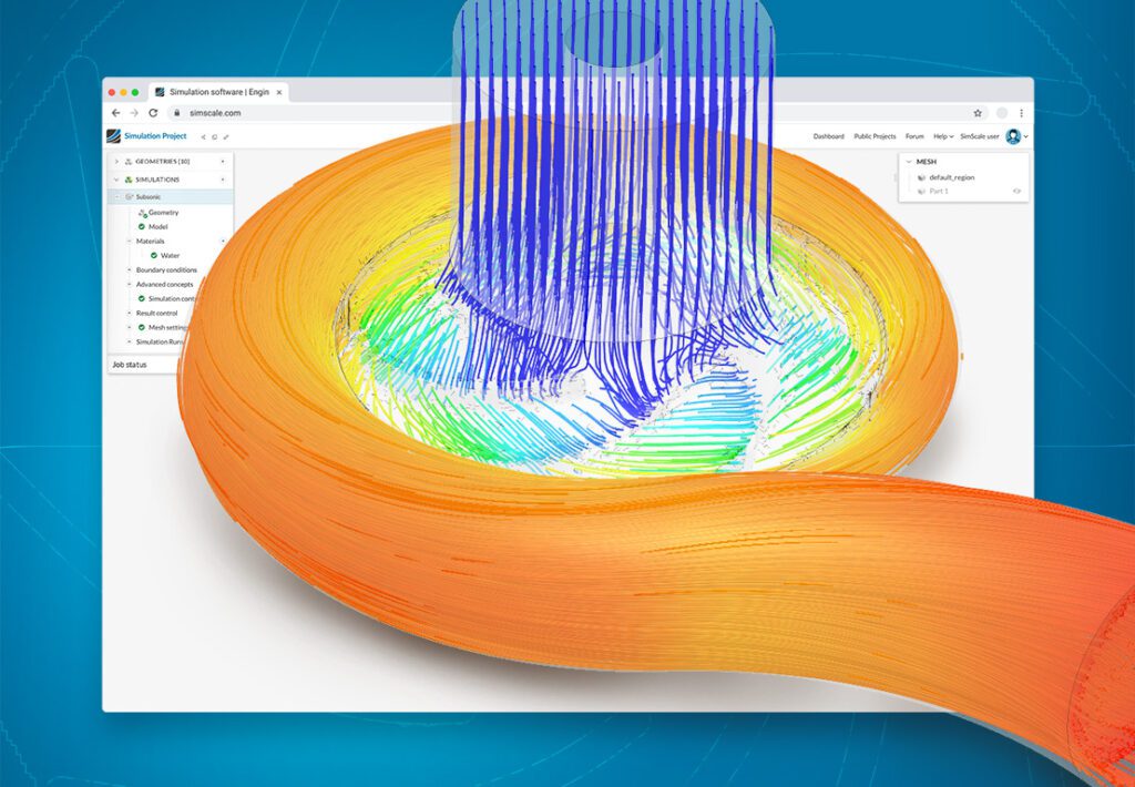
SimScale, a cloud-native engineering simulation software used by global engineering firms, has extended its capabilities in the turbomachinery sector by collaborating with CFturbo to enable turbomachinery modeling. The integration is a coupled workflow between CFturbo and SimScale and is now available in the latest version of CFturbo.
This integration provides functionality for users interested in seamlessly creating CAD models of turbomachinery products such as turbines, pumps, compressors, and fans and running simulations to evaluate their blade profiles, pressure-flow characteristics, and efficiency requirements in SimScale.
CFD & FEA for Turbomachinery Modeling
Utilizing computational fluid dynamics (CFD) and finite element analysis (FEA) presents a valuable methodology for the design and analysis of pumps and turbomachinery systems, encompassing fluid, thermal, and structural behavior. CFD and FEA involve employing mathematical simulations within software programs to replicate the mechanics of fluids and structures, enabling the assessment of realistic assumptions.
These simulations encompass various heat transfer mechanisms, including conduction, convection, and radiation, as well as fundamental fluid behavior such as compressibility and turbulence. Consequently, CFD provides crucial insights into the behavior of moving fluids, offering data on parameters like velocity, temperature, and pressure. It also enables predictions regarding phenomena like cavitation, which arises when inadequate pressure at the pump’s suction end causes liquid to vaporize. In parallel, FEA empowers engineers to calculate loads, stresses, and failure points within pump and turbomachinery designs, facilitating comprehensive structural analysis.
Seamless Workflow from CAD to Simulation
With CFturbo, users can create completely new CAD geometries of turbomachinery products and modify existing designs. CFturbo guides the user step-by-step through the complete design process of a turbomachine, starting from as little as an initial design point as the input.
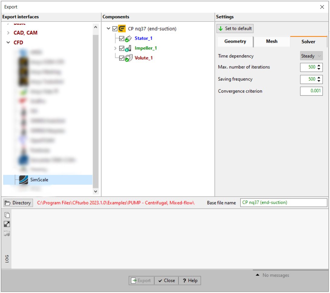
The CFturbo software now includes an export interface that lets its users export geometry from CFturbo and start simulating immediately in SimScale. The workflow is enabled using the SimScale application programming interface (API), which reads the exported 3D STEP file and related model settings from CFturbo and makes these simulation-ready for use in SimScale. Users can then follow the easy-to-use interface in SimScale to run simulations, post-process the results, and create insightful and compelling visualizations.
Key Benefits of the CFturbo-SimScale Combined Workflow
Simulation in the cloud leverages scalable high-performance computing with flexible pricing models and is a cheaper alternative to traditional desktop-based software tools. SimScale users for turbomachinery modeling also benefit from a binary tree-based mesher that results in a high-quality and more efficient mesh compared to competitive tools. The key advantages of using the CFturbo-SimScale combined workflow include:
- Fast simulation time and the ability to perform scenario analysis in parallel using design point parametrization; even for intricate geometries, users benefit from accelerated simulation setup, runtime, and stable simulation convergence that lead to faster insights and design decisions.
- Accurate simulations that allow users to create a full performance curve for a given design point and iterate on the baseline design
- Leveraging the above for design of experiment (DoE) and optimization studies using third-party tools–enabled by the strong APIs in CFturbo and SimScale that come with examples and documentation on how to get started quickly.
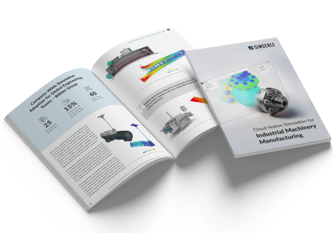
Cloud-Native Simulation for Industrial Machinery Manufacturing
Our latest eBook explores how cloud-native simulation is transforming industrial machinery manufacturing challenges into opportunities. Download it for free by clicking the button below.
Turbomachinery Modeling: From Pump Design to Simulation
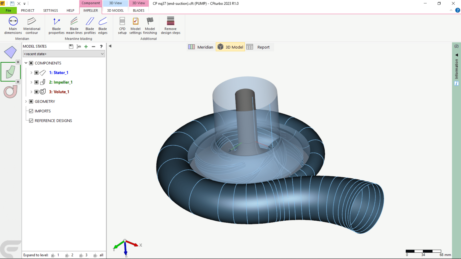
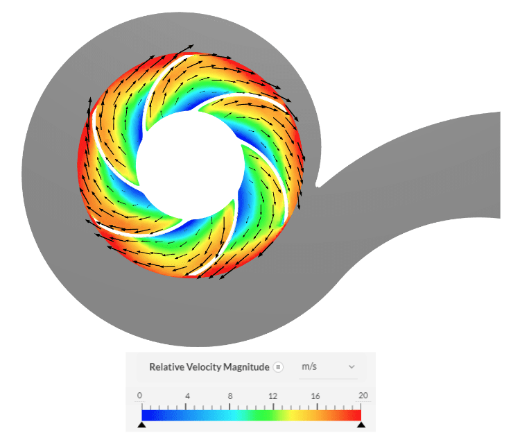
Designing the Pump in CFturbo
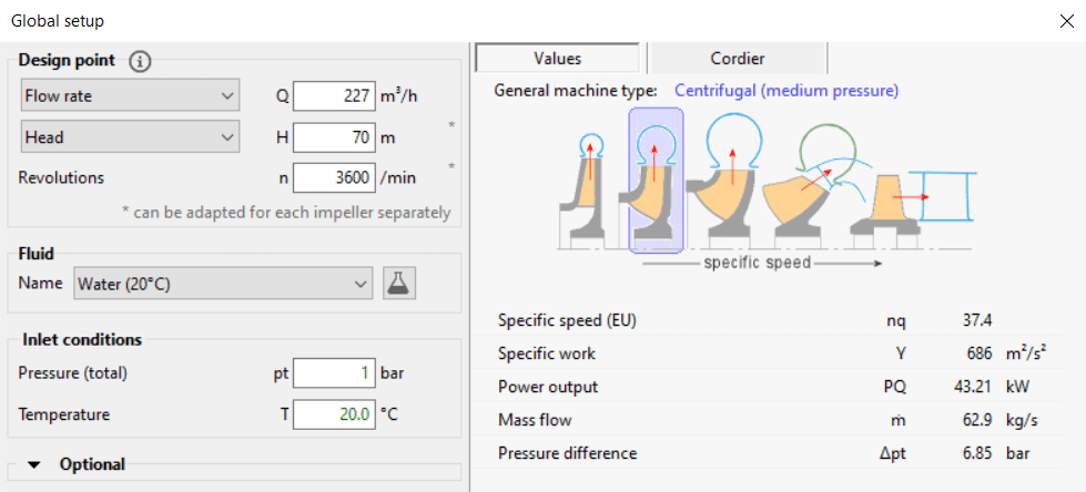
An end-suction close-coupled (ESCC) centrifugal pump is designed in CFturbo. The following design features and operation requirements of the pump’s design point, or best efficiency point (BEP), are used as inputs to rapidly create the pump design from scratch:
| Rotational speed (n) | 3600 RPM |
| Operating Fluid | Water @ 20° C |
| Flow Rate (Qdesign) | 227 m3/hr |
| Pressure head (H) | 70 meters |
With the combination of the design point’s flow rate, pressure head, and rotational speed defined, the corresponding machine type is categorized as a medium-pressure centrifugal pump.
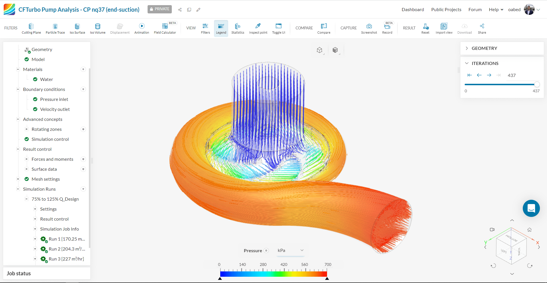
Pump Design Exported to SimScale for Simulation
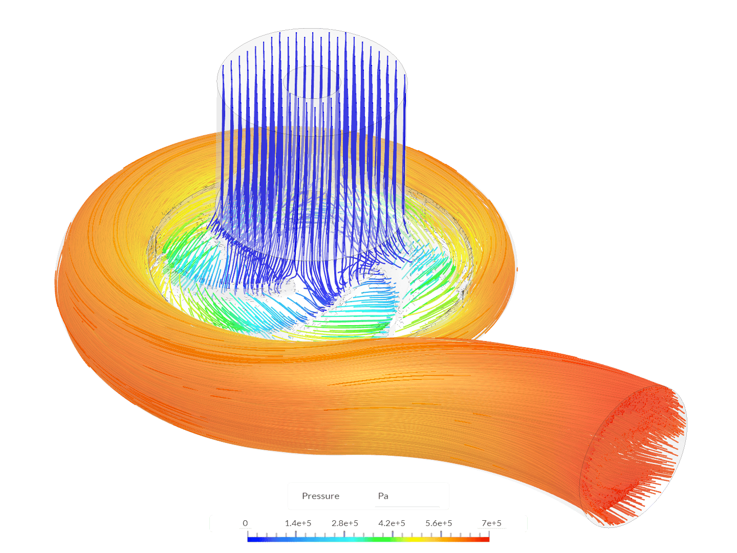
The pump design that is generated based on an ideal design point requirement, however, will not necessarily perform exactly as intended. This is why a simulation tool such as SimScale is needed to predict and validate its actual performance. The CAD model and design conditions are seamlessly exported to SimScale and are ‘simulation-ready’. We have simulated five flow rates in parallel, and a 640K cell mesh is auto-generated when hitting the simulate button:
- The full pump curve of five operating points is run in 40 minutes
- Compute cost of obtaining the full pump curve is 10 core hours (CHs), equating to less than $3 USD of computing cost.
The SimScale Subsonic simulation predicted that the generated pump design’s pressure head at the design point flow rate would be 3.3% less than the specific pressure head.
| Specified Design Point / BEP | Simulated Design Point / BEP | |
| Pressure head (H) | 70 m / 686.3 kPa | 67.7 m / 663.7 kPa |
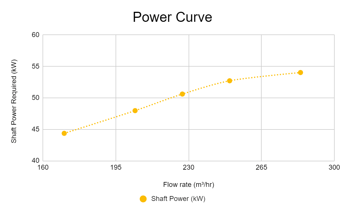
The shaft power and efficiency of the design point / BEP simulation results are as follows:
| Shaft power required | 68.6 horsepower (hp) |
| Hydraulic efficiency at BEP | 82.7% (this is the calculated value using SimScale) |
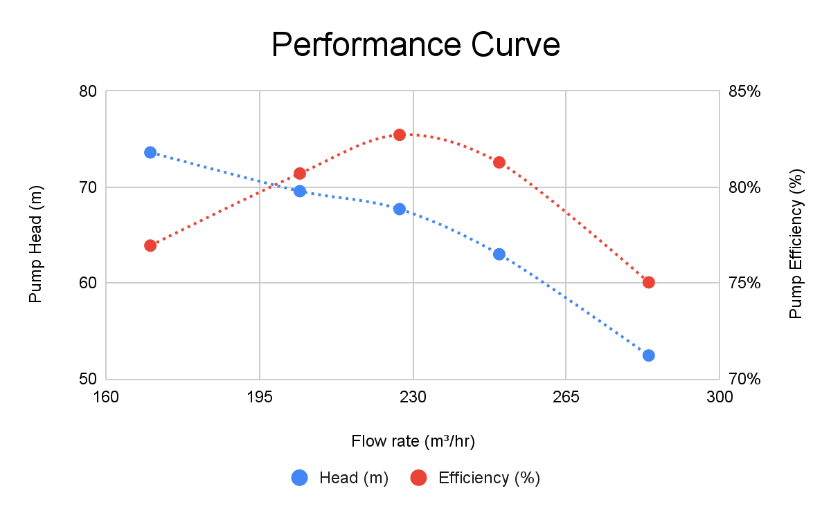
Looking at multiple operating conditions and their corresponding performance, a pump performance curve is generated using SimScale. The set of flow rates used is highlighted below, and the results of the simulation are plotted in the following pump curves.
| Flow Rate (% of Qdesign) | Flow Rate (m3/hr) |
|---|---|
| 75% | 170.25 m3/hr |
| 90% | 204.3 m3/hr |
| 100% | 227 m3/hr |
| 110% | 249.7 m3/hr |
| 125% | 283.75 m3/hr |
Webinar with CFturbo
Watch this webinar where experts from SimScale and CFturbo walk you through the automated design-simulation workflow.