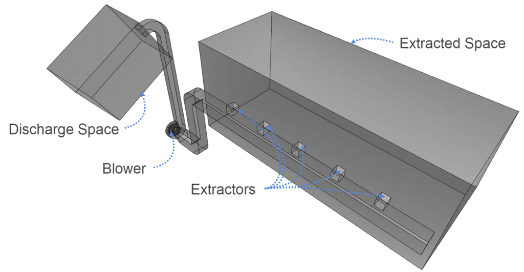
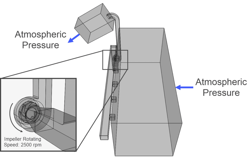
This project shows how CFD can predict the performance of an industrial blower extraction system design, aiding the overall iterative design process. The system to be simulated includes a Ø0.57 m, 8-blade impeller industrial blower, which takes air from a 10×4 m room through 5 extractors.
The extraction of air should be evenly distributed across the 5 extractors within the room in order to remove any potential contaminants effectively and also reduce potential high velocities, above 10 m/s, in the ducting. A minimum flow rate of 2.6 m3/s is required for the blower at a rotating speed of 2500 rpm.
The main objective of this project is then to use CFD through SimScale to evaluate the flow rate distribution across the extractors and the efficiency achieved by the blower for a base design.
How an Industrial Blower System Can Be Set Up for CFD Analysis
The CFD analysis is performed on a 3D CAD model that represents the volume occupied by the air. This 3D geometry can be uploaded as any CAD file format to the browser-based platform (SimScale) and can also be imported from the 3D modelling platform Onshape. Both the extracting space and the discharge space have a face assigned with an atmospheric pressure boundary. The flow rate achieved by the blower at 2500 rpm will be calculated by the solver.
Whitepaper: On-Premises vs. SaaS Simulation: A Comparative Look
This whitepaper addresses the difference between on-premises software and SaaS
solutions for computer-aided engineering, explaining how SaaS came to be and its
key benefits.

Base Industrial Blower Design Results
The simulation takes about one hour until it converges to a stable solution. The results can be processed from a web browser within the SimScale Workbench.
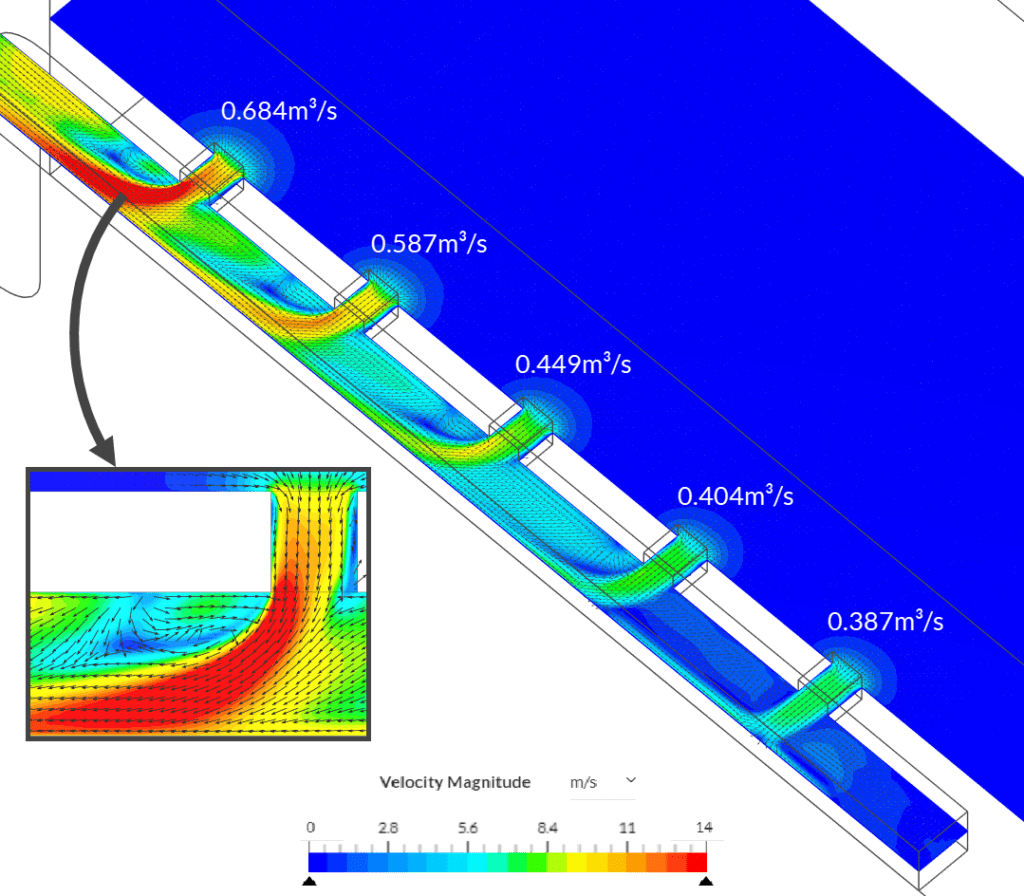
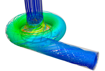
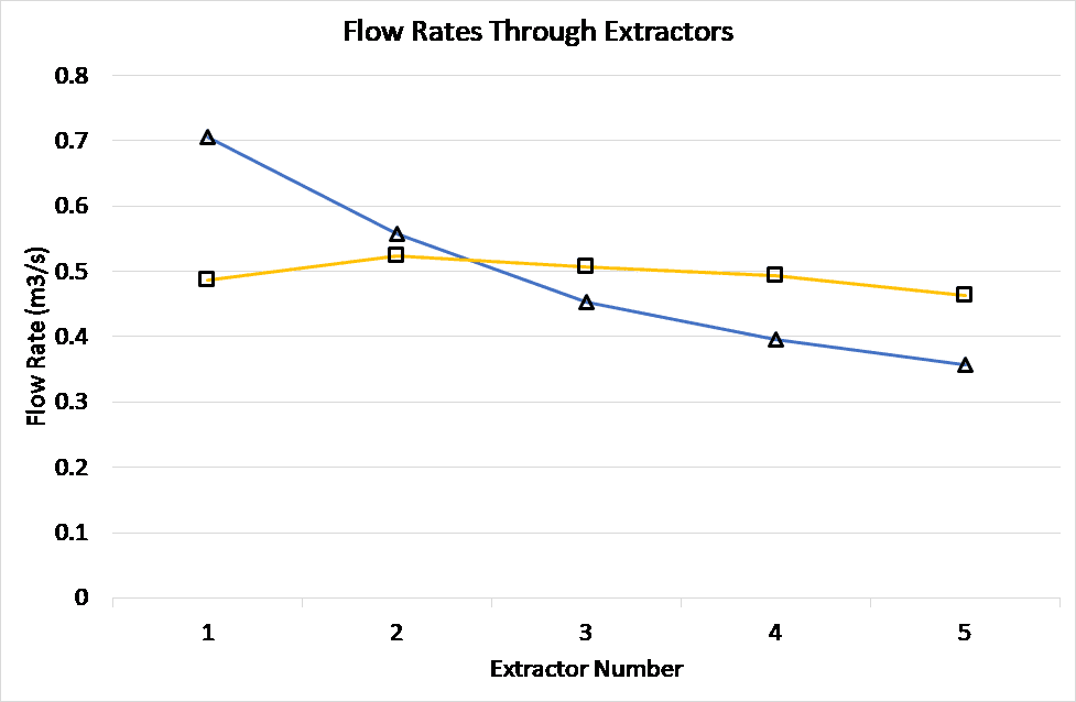
The picture above shows the distribution of the flow rate through the extractors. With each extractor cut through by a velocity map, the large difference (0.6835 m3/s to 0.3835 m3/s) of utilization between the leftmost and rightmost extractors is highlighted. The air in the extractor closest to the blower reaches a velocity above 10 m/s, which indicates an unsuitable design to satisfy the operating conditions stated above. The picture also shows low-velocity regions in the main duct, as well as visible recirculation zones where the air flows back towards the extractors.
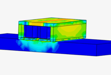
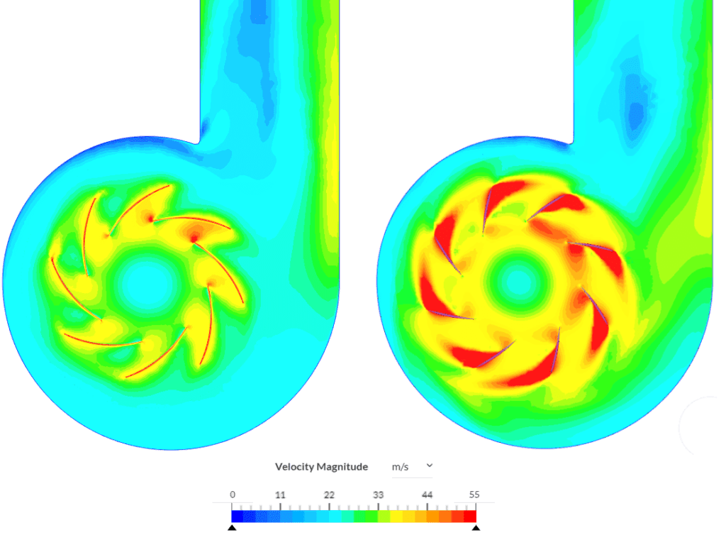
On the blower side, some low-velocity zones past the leading edges of the blades can be observed. This indicates flow separation as the change in incidence angle is too large as the air flows along the blades. It, therefore, hinders the flow performance of the device.
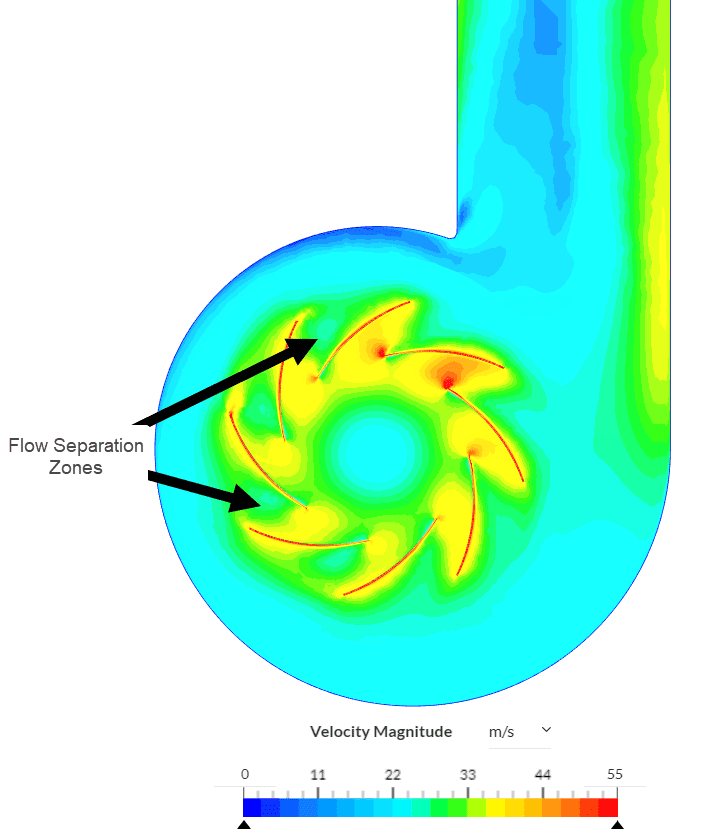
With this base design, the blower capacity is 2.51 m3/s, which is a non-satisfactory condition. Consequently, a new design is proposed so that the flow is better distributed amongst the extractors and the blower produces the required flow rate of 2.6 m3/s.
New Proposed Design for an Industrial Blower
The pictures below show the changes in the industrial blower extraction system, with smoother transitions and large elbows between the extractors and the blower inlet. This is to account for the recirculation and low-velocity phenomenon that could be seen in the original design results. To evenly spread the extraction, the individual ducts from the extractors are merging at one single plenum.
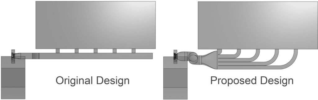
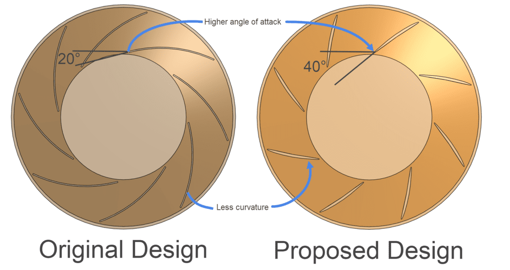
The blower blades’ angle of attack is increased from 20° to 40°. The blades of the proposed design have less curvature as a result of the flow separation phenomenon observed in the base design.
Comparative Results: Original Design vs. Proposed Design
The simulation results show a significant improvement in terms of flow distribution across the extractors with very little variation in flow rate (max 0.07 m3/s difference). Top velocities are also lowered, with a maximum air velocity of about 9 m/s.
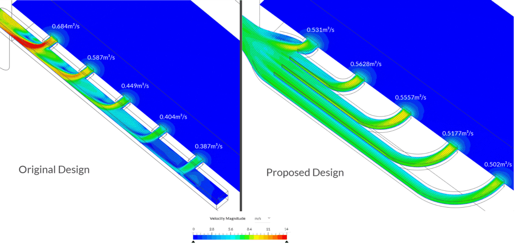
The velocity in the ducts is more evenly distributed, as seen in the velocity cut plane results shown below.
The velocity cut plane through the midplane of the impeller highlights that the improved blower design is capable of generating higher velocities than the base design and therefore achieves a larger flow rate or 2.825 m3/s at a rotational speed of 2500 rpm. The large flow separation on the upper surfaces of the original blades is removed.
Conclusion: Improved Industrial Blower Design
With CFD, evaluating whether a design meets a specific performance requirement has become a straightforward and easily compatible design step for the engineer. With a 3D CAD model and a set of known conditions, the setup replicates a working scenario and the results include velocity distribution, pressure, temperature, and other quantities used for performance assessment.
In this project, an industrial blower system design was numerically simulated. The results produced indicated that the flow rate achieved by the blower was lower than the requirements. The extractor’s utilization was found to be uneven, resulting in velocity above the recommended value for vibration and excessive noise prevention. This led to the proposal of a new design, which was simulated under the same conditions.
The new design included a higher angle of attack and less curvature of the blower as well as a redefinition of the ducting between the extractors and the blower inlet. The results were compared with the base or original design and proved that the new blower system design achieved the desired flow rate of 2.6 m3/s, and the extractor utilization was acceptable, with velocity values lower than 10 m/s.