Blog
Product
What is SimScale?
Cloud Simulation
Discover high-fidelity simulation accessible from anywhere, at any scale.
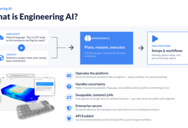
Engineering AI
Discover how SimScale’s Engineering AI transforms simulation workflows
Physics AI
Discover how SimScale’s Physics AI delivers instant engineering predictions
Physics
Fluid Dynamics
Laminar & turbulent,(in)compressible & multiphase flow
Structural Mechanics
Static, dynamic, vibration & thermomechanical analysis
Thermal Simulation
Heat transfer, thermomechanical & thermal management
Electromagnetics
Low-frequency electromagnetics simulations
Technology
Artificial Intelligence (AI)
Learn how AI enables faster simulation
AI Foundation Models
Physics AI foundation models for predictive simulation
API
Customize & automate simulation workflows
Integrations & Partners
How SimScale integrates with your existing workflow
Security
Secure platform with data protection & privacy standards
Simulation Infrastructure Management
Learn how SimScale comes with built-in SPDM capabilities
Simulation Methods
See what’s under the hood of SimScale’s simulation capabilities
Solutions
Use Cases
Scaling Engineering Expertise
Scale expert knowledge across your team with AI.
RFQ Automation
Win more proposals with automated RFQ/RFP workflows.
Agentic Workflow Automation
Automate complex engineering with flexible agentic AI.
See All
Industries
Architecture, Engineering & Construction (AEC)
Meet the demands of modern architecture & sustainability
Automotive & Transportation
Increase automotive engineering innovation & efficiency
Electronics & High Tech
Design more robust & reliable electronics faster
Energy
Test & optimize turbines, pumps, PV systems & more
Machinery & Industrial Equipment
Reduce costs & time-to-market with digital prototyping
Aerospace & Defense
Reduce physical prototyping & increase time to market
Manufacturing
Manufacture products faster and more reliably
See All
Applications
Electronics Thermal Management
Optimize your electronics cooling designs
Indoor Environment
Simulate & optimize indoor environment designs
Multiphase Flow
Simulate multiphase flow with accuracy & speed
Nonlinear Structural Analysis Software
Optimize structural designs with changing stiffness
Turbomachinery
Optimize & improve efficiency of turbomachinery designs
Urban Microclimate
Optimize designs with wind & thermal comfort analysis
Valve
Test & optimize valve designs to increase performance
See All
Resources
Content Hub
Engineering AI
Fuel your strategy with the latest insights, trends and resources
Engineer the Irreplaceable
Explore the SimScale story
Blog
Stay up-to-date with the latest articles
Documentation
Read detailed info on how to use the SimScale platform
Research Reports
Stay up-to-date with the latest engineering trends
Whitepapers
Download & read comprehensive CAE whitepapers
Validation Cases
View experimental/analytical validated simulations
What’s New?
See the latest features & product updates
Community
Forum
Discuss & get help on CAE & SimScale topics
Press Releases
Read our latest press releases & news stories
Webinars & Workshops
Register for upcoming webinars & watch on-demand replays
Academy
Tutorials
View step-by-step user guides for all analysis types
Case Studies
Public Projects
Pricing
Dashboard
View Profile
Manage Account
Cookie Preferences
Log out
Log in
Sign up
Product
What is SimScale?
Cloud Simulation
Discover high-fidelity simulation accessible from anywhere, at any scale.
Engineering AI
Discover how SimScale’s Engineering AI transforms simulation workflows
Physics AI
Discover how SimScale’s Physics AI delivers instant engineering predictions
Physics
Fluid Dynamics
Laminar & turbulent,(in)compressible & multiphase flow
Structural Mechanics
Static, dynamic, vibration & thermomechanical analysis
Thermal Simulation
Heat transfer, thermomechanical & thermal management
Electromagnetics
Low-frequency electromagnetics simulations
Technology
Artificial Intelligence (AI)
Learn how AI enables faster simulation
AI Foundation Models
Physics AI foundation models for predictive simulation
API
Customize & automate simulation workflows
Integrations & Partners
How SimScale integrates with your existing workflow
Security
Secure platform with data protection & privacy standards
Simulation Infrastructure Management
Learn how SimScale comes with built-in SPDM capabilities
Simulation Methods
See what’s under the hood of SimScale’s simulation capabilities
Solutions
Use Cases
Scaling Engineering Expertise
Scale expert knowledge across your team with AI.
RFQ Automation
Win more proposals with automated RFQ/RFP workflows.
Agentic Workflow Automation
Automate complex engineering with flexible agentic AI.
See All
Industries
Architecture, Engineering & Construction (AEC)
Meet the demands of modern architecture & sustainability
Automotive & Transportation
Increase automotive engineering innovation & efficiency
Electronics & High Tech
Design more robust & reliable electronics faster
Energy
Test & optimize turbines, pumps, PV systems & more
Machinery & Industrial Equipment
Reduce costs & time-to-market with digital prototyping
Aerospace & Defense
Reduce physical prototyping & increase time to market
Manufacturing
Manufacture products faster and more reliably
See All
Applications
Electronics Thermal Management
Optimize your electronics cooling designs
Indoor Environment
Simulate & optimize indoor environment designs
Multiphase Flow
Simulate multiphase flow with accuracy & speed
Nonlinear Structural Analysis Software
Optimize structural designs with changing stiffness
Turbomachinery
Optimize & improve efficiency of turbomachinery designs
Urban Microclimate
Optimize designs with wind & thermal comfort analysis
Valve
Test & optimize valve designs to increase performance
See All
Resources
Content Hub
Engineering AI
Fuel your strategy with the latest insights, trends and resources
Engineer the Irreplaceable
Explore the SimScale story
Blog
Stay up-to-date with the latest articles
Documentation
Read detailed info on how to use the SimScale platform
Research Reports
Stay up-to-date with the latest engineering trends
Whitepapers
Download & read comprehensive CAE whitepapers
Validation Cases
View experimental/analytical validated simulations
What’s New?
See the latest features & product updates
Community
Forum
Discuss & get help on CAE & SimScale topics
Press Releases
Read our latest press releases & news stories
Webinars & Workshops
Register for upcoming webinars & watch on-demand replays
Academy
Tutorials
View step-by-step user guides for all analysis types
Case Studies
Public Projects
Pricing
Dashboard
View Profile
Manage Account
Cookie Preferences
Log out
Sign up
Log in
Featured
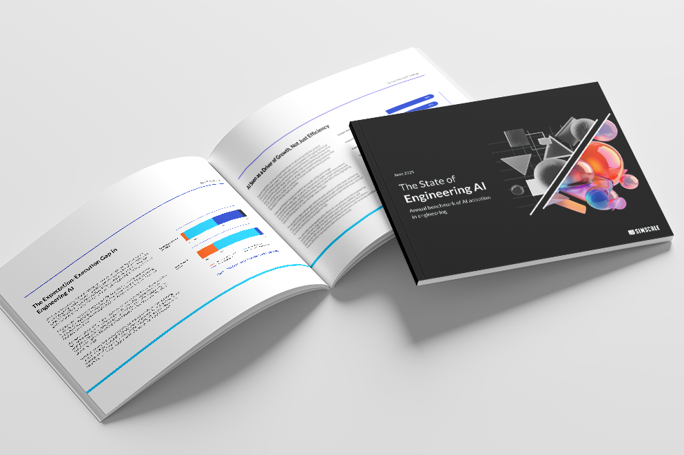
The Engineering AI Ambition-Execution Gap: What Our New Global Survey Reveals
David Heiny
June 27th, 2025
Read Time
4 minutes
Learn More
Featured
Engineer the Irreplaceable — Why This Idea Matters So Much to Me
David Heiny
June 20th, 2025
Read Time
3 minutes
Learn More
Featured
What a Year for Our ESG Journey!
Matias Degiuseppe
March 18th, 2025
Read Time
3 minutes
Learn More
Featured
Top 5 Webinar Highlights: Real-Time Simulation with AI
Samir Jaber
February 25th, 2025
Read Time
5 minutes
Learn More
Featured
Top 5 Webinar Highlights: Automating Simulation Workflows
Samir Jaber
February 21st, 2025
Read Time
5 minutes
Learn More
Featured
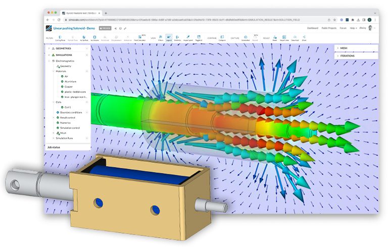
Solenoid Design and Modeling with Cloud-Native Simulation
Nur Ozturk
February 7th, 2025
Read Time
10 minutes
Learn More
Featured
Top 5 Webinar Highlights: Hexagon’s Marc Solver Now on the Cloud
Samir Jaber
February 5th, 2025
Read Time
5 minutes
Learn More
Featured
Student Success Story: Team Tampere Formula Student
Satvik Shenoy
January 24th, 2025
Read Time
6 minutes
Learn More
Latest
Latest
Popular
Latest Articles
SimScale Workflows: Why we are opening up the platform (& why you should care)
News
SimScale Advantages
Alex Graham
May 29th, 2026
Read Time
4 minutes
Data Center Cooling: Four Lessons from Teams That Simulate Before They Build
Alex Graham
May 19th, 2026
Read Time
12 mins
How Agentic Engineering is Reshaping Simulation-Driven Product Design — Key Takeaways
Alex Graham
May 18th, 2026
Read Time
5 mins
How Drone Teams Use CFD and FEA Simulation to Ship Faster
Aerodynamics
Batteries
Drones
Structural Mechanics
Alex Graham
May 15th, 2026
Read Time
10 mins
How SimScale’s AI Agent Transforms Simulation Workflows
Agentic Engineering
News
SimScale Advantages
Alex Graham
May 13th, 2026
Read Time
4 mins
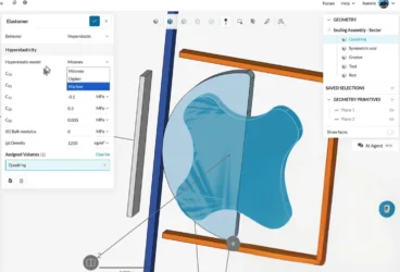
How to Run a Non-Linear Rubber Simulation: Bidirectional Sealing System Walkthrough
SimScale Advantages
Ioannis Tsavlidis
May 6th, 2026
Read Time
5 minutes
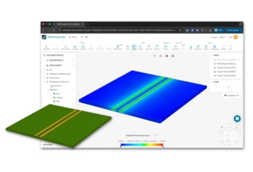
PCB Parasitic Extraction: Signal Integrity Simulation for High-Speed Designs
Nur Ozturk
April 17th, 2026
Read Time
9 minutes
CFD Ventilation Simulation for HVAC Systems and Buildings
Heating, Ventilation, and Air Conditioning (HVAC)
Product Design
Peter Selmeczy
April 17th, 2026
Read Time
7 Minutes
1
2
3
4
5
6
…
55
Next »
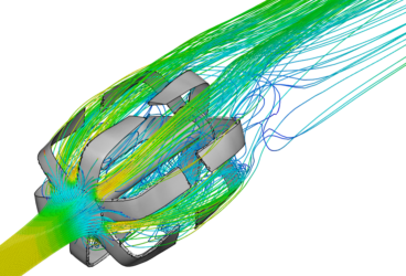
Whats new in CFD?
Data Center Cooling: Four Lessons from Teams That Simulate Before They Build
Alex Graham
May 19th, 2026
Read Time
12 mins
CFD Ventilation Simulation for HVAC Systems and Buildings
Peter Selmeczy
April 17th, 2026
Read Time
7 Minutes
Virtual Wind Tunnel Online: Cloud-Based Simulation
Peter Selmeczy
March 31st, 2026
Read Time
9 Minutes
Guide to CFD Analysis: Process, Steps & Applications
Peter Selmeczy
March 31st, 2026
Read Time
9 Minutes
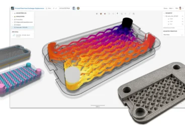
Cold Plate Cooling Design
Alexander Fischer
December 5th, 2025
Read Time
6 minutes
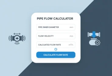
Pipe Flow Calculator
Peter Selmeczy
October 17th, 2025
Read Time
3 minutes
Lift Coefficient Calculator
Peter Selmeczy
October 17th, 2025
Read Time
4 minutes
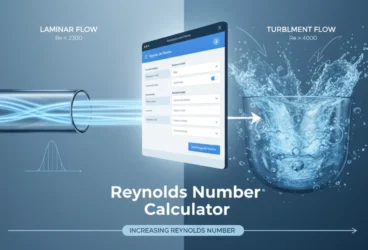
Reynolds Number Calculator
Peter Selmeczy
October 17th, 2025
Read Time
5 minutes
Stay updated and never miss an article!
Please enable JavaScript to view the form.
×
Sign up for SimScale
and start simulating now
Please enable JavaScript to view the form.