A multiphysics approach to design is of the essence to fully capture the real-world interactions between the physical phenomena at play inside today’s complex products. This means that to develop the best products, engineers need simulation tools capable of handling structural, thermal, and fluid flow behavior with high fidelity and in a timely manner. In this case study, a globe valve geometry is used to run a multiphysics analysis to predict performance and reduce the pressure drop by minimizing regions of recirculation, which saves on the energy cost needed to operate the valve.
Case Study: Globe Valve Optimization
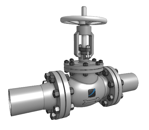
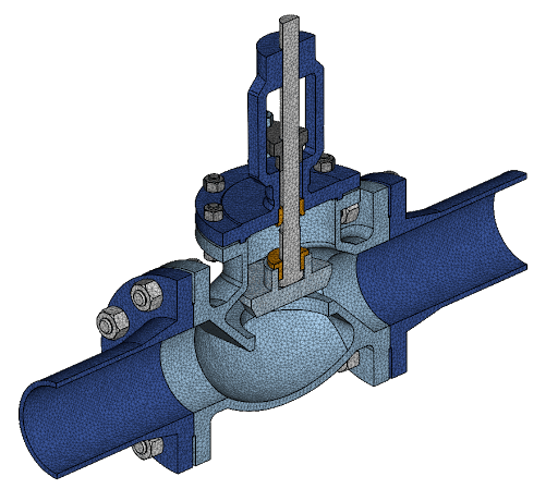
In this case study, simulation specialists were tasked with evaluating the performance of the current configuration of a globe valve and proposing improvements for the next design iteration. The subject is a DN100 (4 inches), class 150#, raised face flange, carbon steel globe valve.
Performance of the valve was predicted across three metrics:
- Flow performance, measured in terms of the pressure drop curve as a function of flow rate, and cavitation severity for off-design operating conditions.
- Stress safety factor, measured as the ratio of the developed effective stress to the code allowable stress, in the case of pressure burst and thermal shock.
- Heat dissipation, measured as the temperature distribution in the valve under operating flow conditions.
In order to compute the quantities of interest described above, three simulation types will be performed:
- Incompressible flow, using the Multi-purpose solver, with a parametric sweep of the flow rate to obtain the pressure drop curve
- Nonlinear static, with elasto-plastic materials and a pressure burst load
- Nonlinear transient thermo-mechanical, with convective internal heat load and convective external dissipation.
After the results are obtained and analyzed, they can be used to propose design changes and thus move forward to the next design iteration. The flexibility and power of SimScale allow engineers to perform such tasks in hours rather than days.
Simulation Setup
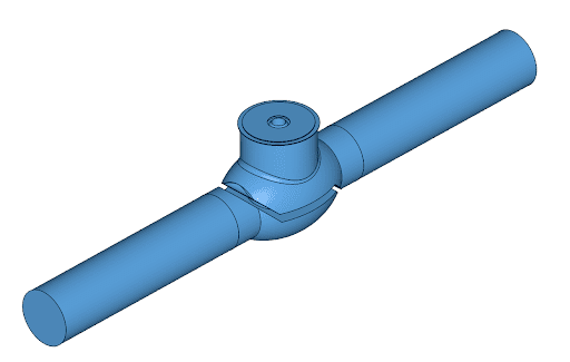
The overall workflow for a simulation project in SimScale starts with a 3D CAD model. In this case study, we start from the model as can be seen in the figure above, and then proceed as follows:
- Import CAD model into the Workbench,
- Use the CAD Edit Mode to clean up and optimize the geometry for simulation,
- Create, set up, and run the flow simulation,
- Create, set up, and run the pressure burst simulation,
- Create, set up, and run the thermo-mechanical simulation,
- Post-process the results as each simulation finishes.
CAD Edit
SimScale’s CAD mode allows engineers to start from an almost production-ready model and optimize it for simulation. In this case, as we will perform both flow and structural simulations, two models are derived from the original CAD.
First, for the flow model, we perform a Flow Volume Extraction operation to create a part filling the fluid region, which in our original model is void. Then, we can remove all the solid parts to leave only the flow region. A final adjustment is made by extending the inlet and outlet faces so that we have proper lengths to develop the flow profile and a more stable simulation.
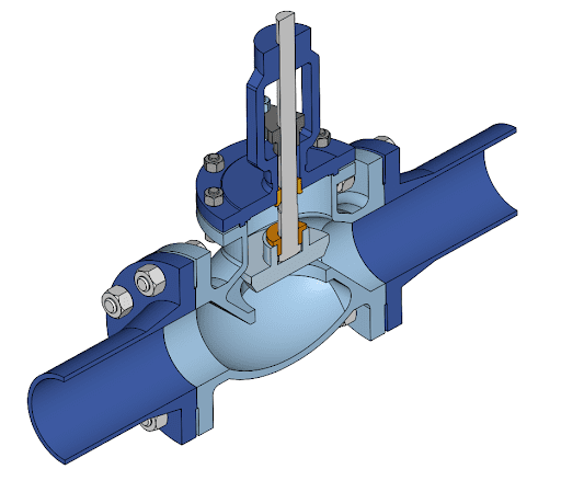
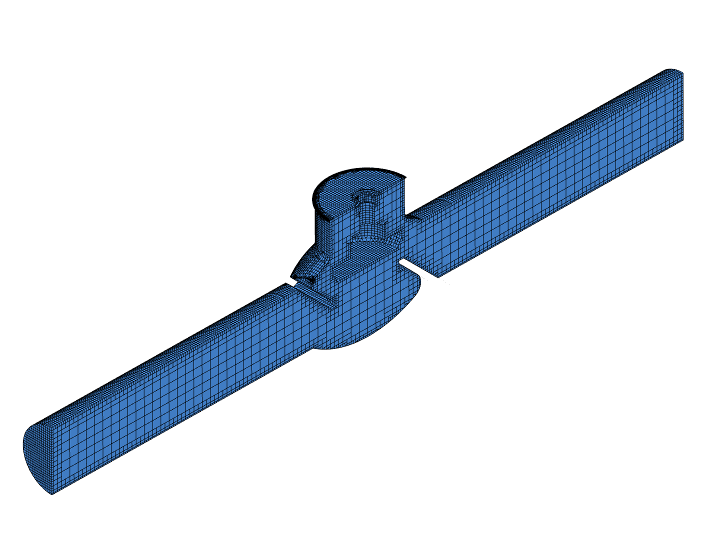
Second, for the structural simulations, we will leverage the symmetry to mesh only half the model. This is done by performing a Body – Split operation and will allow us to save on computational resources. Also, unnecessary parts at the top are removed.
Flow Simulation
For the computation of the pressure drop curve, we will make use of SimScale’s Multi-purpose solver. This solver features automatic Cartesian mesh generation, as well as fast and accurate computation of the results. The simulation is set up as follows:
- Turbulent flow with custom k-epsilon model
- Incompressible flow
- Flow rate-driven flow with volumetric flow inlet and pressure outlet
- Parameterized flow rate to take into account 5 operating points
- Pressure drop measurement between inlet and outlet
- Cavitation modeling for off-design, high flow rate condition
The parametric run for the inlet flow rate is used to compute all the operating points in parallel leveraging the capacity of cloud computing. Results are then aggregated and presented into a pressure drop versus flow rate curve.
Mechanical Simulation
In the purely mechanical simulation, we will investigate the safety factors and stresses developed in the valve assembly due to the principal load, which is the internal pressure. A non-linear static simulation is selected in order to be able to take into account the plasticity of the carbon steels under a pressure burst load:
- Non-linear static simulation
- Elasto-plastic bilinear material curve based on ASME Code properties
- Bolt preload taken into account on the flanged connections
- Internal pressure ramped from zero to six times the rated pressure
Thermo-Mechanical Simulation
Finally, in the thermo-mechanical simulation, we will investigate the heat dissipation produced at the valve, when carrying the heat from forced convection with the internal fluid to the natural convection at the exterior. Additionally, the multiphysics solver allows us to compute the thermal stresses developed in the materials.
- Coupled thermo-mechanics simulation, quasi-static transient with nonlinear behavior
- Elasto-plastic materials reused from the mechanical simulation, including thermal properties from the ASME Code
- Heat load as a thermal convection to the hot fluid
- Heat dissipation as a thermal convection to the exterior
- Bolt preload is taken into account on the flanged connections
- Internal pressure at the rated operating value
Simulation Results
The turn-around time from CAD upload to results is just under three hours. In total, seven simulations are run in parallel, in the cloud. This means that our workstation is free to perform other tasks in the meantime. We can post-process the results as they are ready, without interrupting or having performance hits from the other running simulations clogging our resources.
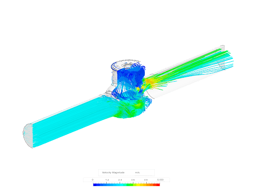
Our first results are from the pressure drop study. Here we can see the streamlines and examine them in local detail for vortex formations and other flow artifacts of interest:
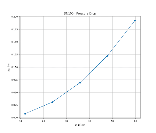
We can also have a look at the pressure-loss curve. In this case, we downloaded the results and processed the data locally in Python for units conversion and plotting:
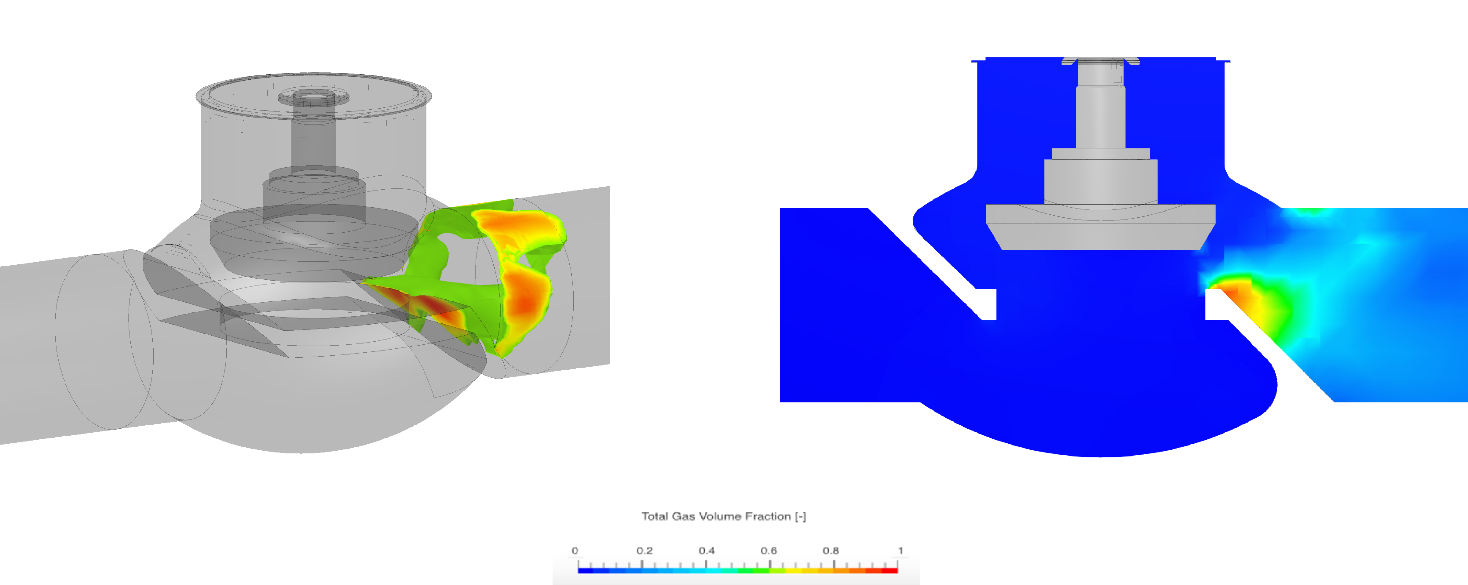
Further, investigating the valve performance at a flow rate above the maximum typical operating point of 60 m3/hr, cavitation effects need to be taken into account. Cavitation in valve assemblies is a result of liquid flow acceleration around the valve opening, dropping the pressure below the liquid’s vapor pressure. These cavities, or vapor bubbles, collapse when pressure rises again downstream, and can result in excessive vibration, noise, and deterioration of the valve assembly & flow performance.
The Multi-purpose solver is capable of cavitation modeling; when toggled on, the cavitation severity, measured by the Total Gas Volume Fraction scalar quantity, can be assessed for off-design operating points, such as high flow rates or high-pressure drops.
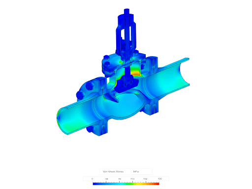
For the pressure burst, we visualize the distribution of the von Mises stress as seen below. From inspecting other fields, we can see that at the maximum internal pressure analyzed, no plasticity is found to occur:
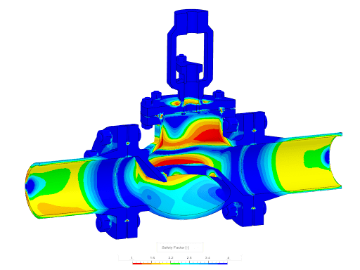
Another interesting visualization is the safety factor against the allowable stress from the Code. With this tool, we can identify regions where we should add some material, for example, by increasing a fillet radius, to reduce the stress levels and increase the safety factor:
Finally, let’s have a look at the temperature distribution in the globe valve after ten seconds of hot flow and natural convection:
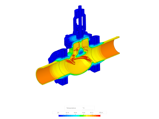
We can identify the regions of higher temperature and also of high-temperature gradients. This information is very valuable to decide on design changes in the case that the cooling performance needs to be improved.
Faster Innovation with Multiphysics Simulation
Based on the simulation results acquired we can use our judgment and make design decisions to modify the valve. In less than one day, we can test multiple design iterations with the power of cloud computing in the SimScale platform, drastically reducing the development time of our mechanical product.


