Water turbines are critical in mankind’s pursuit of clean energy. Among these, the Pelton turbine, inspired by the ingenuity of Lester Pelton, shines for its simplicity and power, which make it especially suitable for extracting energy from high-altitude water sources.
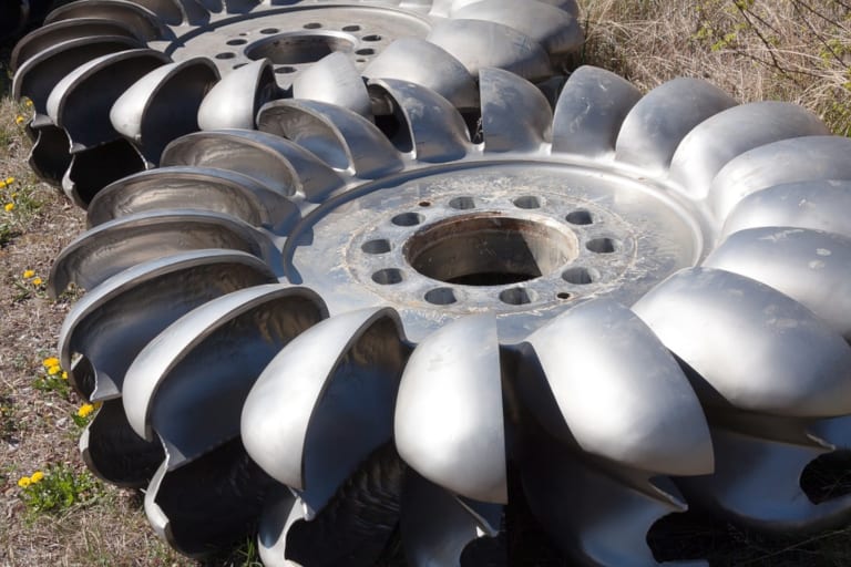
Pelton turbines are characterized by their distinctive spoon-shaped buckets that efficiently capture the momentum of high-velocity water jets in high-head hydroelectric projects. But what differentiates the Pelton turbine in the spectrum of hydroelectric technologies? And how are current technological advancements, particularly cloud-based simulation platforms, revolutionizing the design, optimization, and operational processes of Pelton turbines?
This article delves into the intricacies of Pelton turbines, tracing their origins, understanding their mechanics, and exploring the role of advanced computation simulations, such as those offered by SimScale, in enhancing their performance.
Understanding Pelton Turbines
What is a Pelton Turbine?
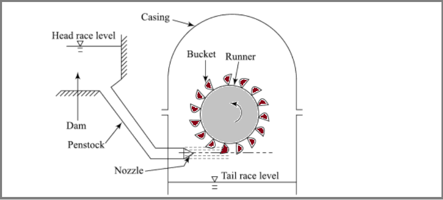
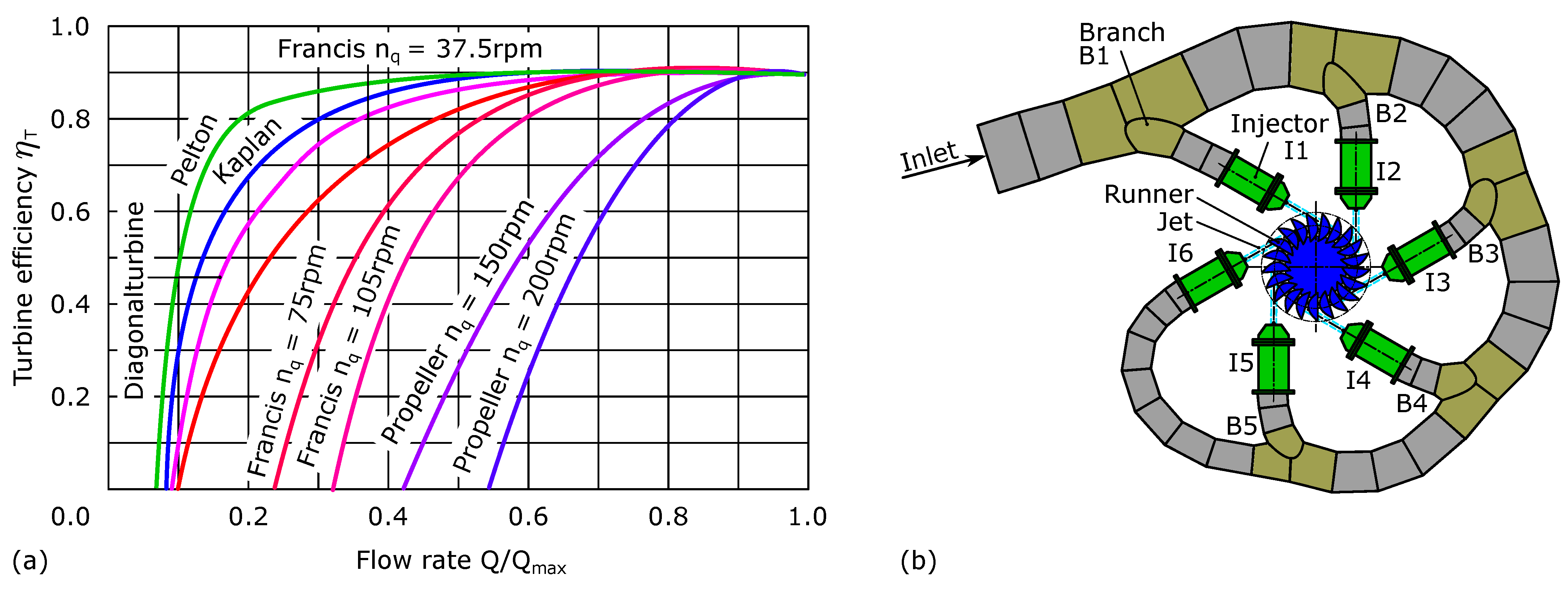
A Pelton turbine, also known as a Pelton wheel turbine, is an impulse turbine uniquely designed to convert the kinetic energy of water into mechanical energy. Unlike its counterparts – the Francis and Kaplan turbines, which are reaction turbines suited for lower-head and higher-flow applications – the Pelton turbine operates efficiently in high-head, low-flow conditions typical of mountainous terrains. It achieves this by directing high-velocity water jets at a series of buckets mounted around the wheel, known as the runner, capturing the water’s momentum with remarkable efficiency.
Historical Background and Modern Applications
Invented in 1880 by Lester A. Pelton, the Pelton turbine has become a cornerstone of modern hydropower technology [1]. With the global installed capacity of hydropower reaching 1330 GW in 2021 and expected to grow significantly by 2050, Pelton turbines are at the forefront of this expansion [2]. They are renowned for their high efficiency, which can reach up to 92%, and continue to be refined for even greater performance.
In modern applications, Pelton turbines are not just confined to large-scale hydropower plants. They are also instrumental in small-scale installations, particularly in remote and mountainous regions where their high-head, low-flow operation is optimal. Furthermore, they are increasingly integrated into smart grid systems, contributing to a more responsive and sustainable electricity network. Pelton turbines also play a pivotal role in managing environmental flows, ensuring that water usage for power generation balances ecological and human needs.
Key Components of a Pelton Turbine
- The Bucket Design: The buckets of a Pelton turbine are its defining feature. They are engineered to split the water jet, ensuring maximum energy transfer from water to the turbine and allowing for efficiencies to remain high, even when operating at part load.
- The Nozzle: The nozzle, or injector, is responsible for regulating the water flow rate. It is designed to maintain high efficiency across a range of operating conditions, ideally keeping Pelton turbine efficiency above 90% until the flow rate is reduced to 20% of the design flow rate [3].
- The Runner and Casing: The runner, with its mounted buckets, is enclosed within a casing to protect and streamline the operation. The turbine’s axis configuration, whether horizontal (with up to two injectors) or vertical (with as many as six injectors), affects the load distribution and efficiency. The design also includes a deflector for emergency shutdowns or to prevent damage.
Pelton turbines are adaptable to horizontal and vertical axis configurations, with the choice impacting the turbine’s load distribution and potential for energy loss due to friction and windage. Their ability to operate efficiently across a wide range of conditions makes them a versatile choice for hydropower installations, especially in areas with high heads and low flows, such as aqueducts or ecological flows from dams.
How Pelton Turbines Work?
Pelton turbines derive their efficiency from the basic principle of impulse, where pressurized water is directed through a penstock and expelled via a carefully sized nozzle to generate a high-speed water jet. The turbine wheel, featuring strategically positioned double-cupped buckets, efficiently captures and redirects this water jet. Upon impact, the water undergoes a rapid change in momentum, transferring its kinetic energy to the turbine wheel and inducing rotation. The rotating turbine wheel is connected to a generator, converting the mechanical energy into electrical power. This synchronized process ensures continuous and reliable power generation.
The hydraulic efficiency of a Pelton wheel turbine is typically calculated using the following formula:
$$ Hydraulic\:Ef\!ficiency = \left(\frac{Mechanical\:Power\:Out\!put}{Hydraulic\:Power\:In\!put}\right) × 100 $$
It is also referred to as the Power Coefficient and is expressed as follows:
$$ \eta = \frac{P_t}{P_w} $$
where \(\eta\) is the hydraulic efficiency, \(P_t\) is the turbine power output, and \(P_w\) is the water head (unconstrained water current).
This formula quantifies the efficiency of the turbine in converting the hydraulic power of the incoming water into mechanical power. The mechanical power output is the electrical power generated by the turbine, while the hydraulic power input is the energy carried by the water jet.
Pelton turbines, with their distinctive design and efficient water-to-wheel energy transfer, often yield hydraulic efficiencies in the range of 85% to 90%. This means that a significant proportion of the water’s kinetic energy is successfully harnessed to produce electrical power. Yet, this efficiency may drop or fluctuate depending on influencing factors, such as windage, mechanical friction, backsplashing, and nonuniform bucket flow.
Advancements in Pelton Turbine Design Through Simulation
The integration of engineering simulation technologies, notably Computational Fluid Dynamics (CFD), has transformed the design and analysis of Pelton turbines. This innovative approach allows for the detailed modeling of water flow dynamics within the turbine, providing engineers with the insights needed to enhance efficiency and precision in turbine designs. As we delve deeper into the specifics, we will explore how Pelton turbine simulation serves as a crucial foundation for design refinement, performance prediction, and, ultimately, the realization of more sophisticated and efficient Pelton turbine systems.
Engineering simulations are pivotal during the early stages of the design cycle of Pelton turbines, acting as virtual proving grounds. They enable the testing of various design concepts, material choices, and operational conditions without the need for physical prototyping. This stage is essential for pinpointing potential design flaws and implementing improvements, thereby conserving time and resources.
Optimizing Pelton Turbine Designs with CFD
CFD simulations offer a robust framework for tackling fluid flow challenges, allowing for the creation of three-dimensional models of Pelton turbines. These models provide a window into the intricate interactions between water jets and turbine buckets, facilitating the optimization of bucket design, nozzle placement, and runner shape to achieve high turbine efficiency.
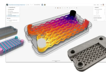
This is where a simulation tool like SimScale CFD plays a key role. Not only does this tool provide accurate simulation capabilities, but it also offers parallelization by leveraging cloud computing and storage. In other words, multiple simulations can run in parallel without limitations imposed by hardware constraints. This saves significant time during the design process and enables design parameterization and efficient testing. More on this is discussed below.
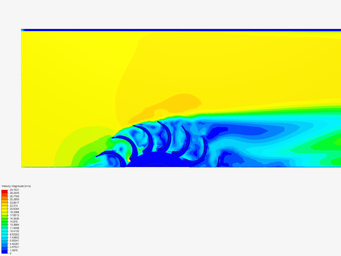
Dynamic Visualization and Performance Forecasting in Pelton Turbine Simulation
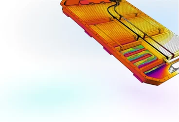
A key benefit of CFD simulations is the dynamic visualization of water flow through the turbine blades, offering more than just static imagery. Engineers can track the formation and impact of water jets on the buckets, observing the resulting flow paths. This dynamic analysis is crucial for identifying and rectifying inefficiencies. Furthermore, simulations enable turbine performance prediction across a spectrum of conditions, allowing engineers to anticipate real-world functionality and ensure the most efficient and dependable operation of a Pelton turbine.
Cloud-Native Simulation for Industrial Machinery Manufacturing
Our latest eBook explores how cloud-native simulation is transforming industrial machinery manufacturing challenges into opportunities. Download it for free by clicking the button below.
Cloud-Native CFD to Accelerate Pelton Turbine Innovation
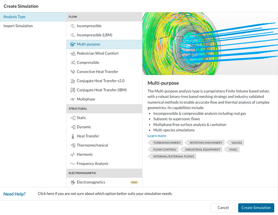
SimScale’s Multi-purpose Analysis for CFD Simulation of Pelton Turbines
In Simscale, the most useful CFD analysis type to simulate Pelton turbines is Multi-purpose Analysis. The Multi-purpose analysis type introduces an automated and robust meshing strategy tailored for fluid flow applications like Pelton Turbines. This approach generates hexahedral cells optimized for the underlying solver, significantly reducing mesh generation times. The resultant high-quality mesh requires fewer cells to achieve comparable accuracy, leading to faster convergence. It is important to note that this efficiency may come with a reduction in the feature set.
Key features of the mesher include body-fitted Cartesian meshing, cells suitable for finite volume discretization, and a highly parallelized meshing algorithm for rapid processing.
The Multi-purpose solver in SimScale is a Finite Volume-based CFD solver, employing a segregated pressure-velocity coupling mechanism. It stands out for its ability to simulate both incompressible and compressible flows, accommodating laminar or turbulent conditions all in one place. It also offers versatility by supporting both steady-state and extensive transient analyses. As for turbulence modeling, the analysis relies on the Reynolds-Averaged Navier-Stokes (RANS) equations, employing the k-epsilon turbulence model for closure and proprietary wall functions for effective near-wall treatment, making it particularly suited for Pelton Turbines.
Enhancing Pelton Turbine Design with SimScale’s Predictive Analysis
SimScale’s simulation capabilities bring a new level of sophistication to the design and optimization of Pelton turbines. Across numerous projects hosted on the platform, SimScale users are harnessing the power of cloud-native CFD simulation to enhance the operational efficiency and reliability of these turbines.
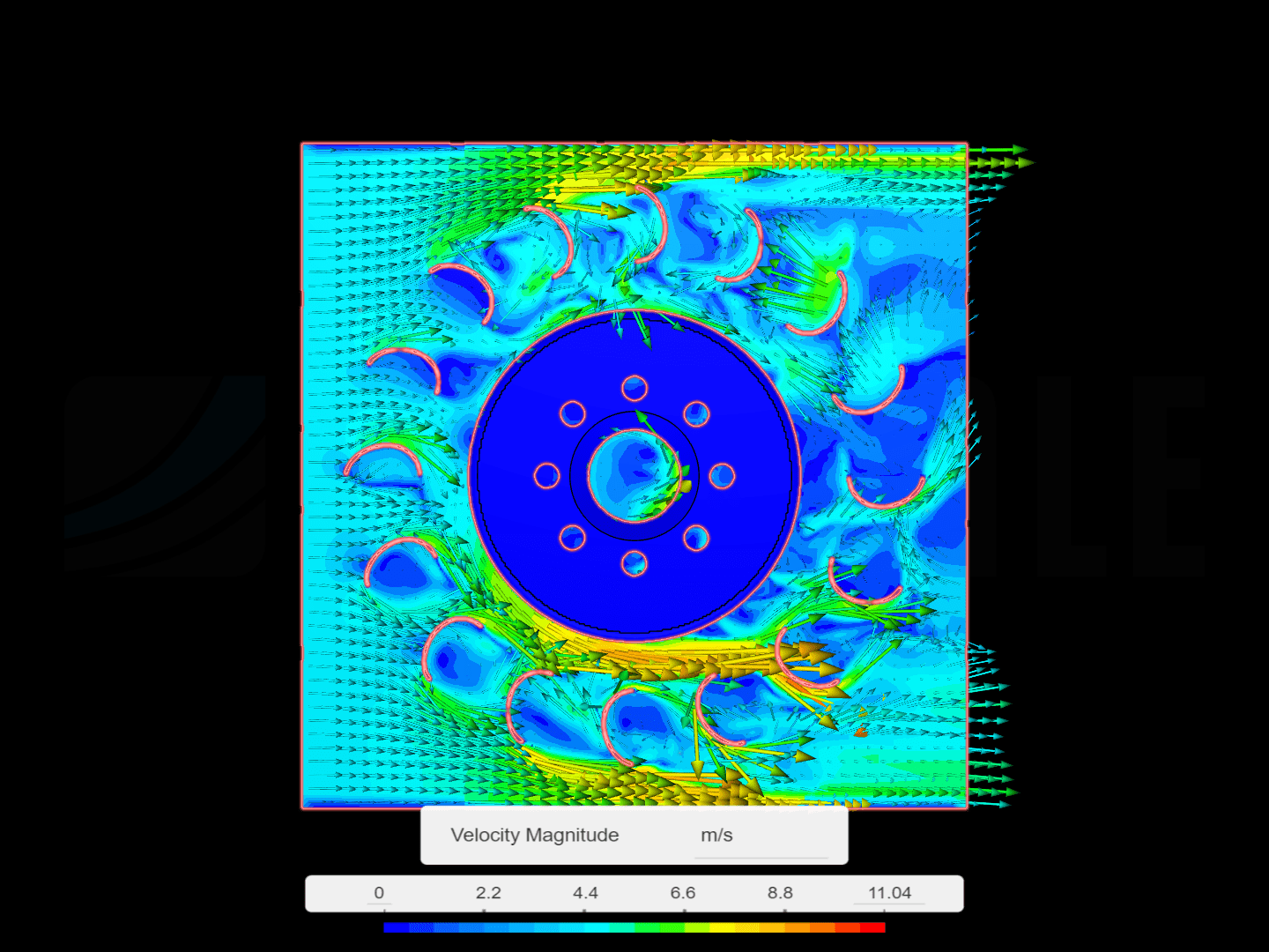
One such project studied the water flow within a Pelton turbine, mapping velocity magnitudes throughout the turbine’s buckets. This analysis provided a detailed visualization of flow dynamics, enabling the identification of optimal flow conditions and guiding improvements to the turbine design for increased energy conversion efficiency.
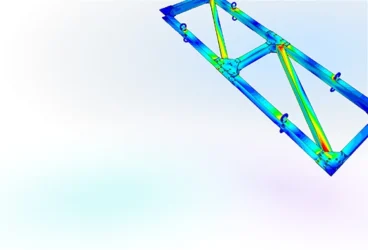
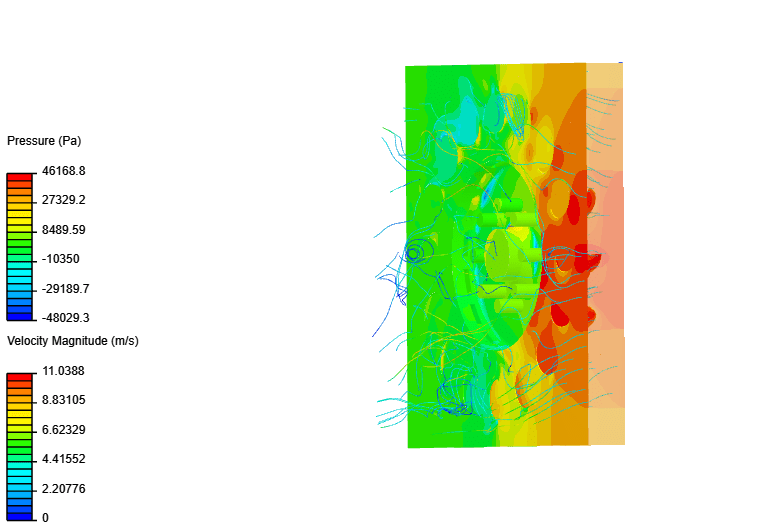
In another study, the focus was placed on understanding the pressure distribution within the turbine. The simulations executed in SimScale offered a three-dimensional perspective on the pressure loads the turbine blades endure, which is fundamental for assessing the turbine’s structural integrity and ensuring its longevity under high-stress conditions.
Through these projects, SimScale has proven to be an invaluable tool for predictive analysis that is vital for the refinement of turbine designs. It enables engineers to virtually prototype and test their concepts, iterate designs with accuracy, and achieve a level of detail that significantly reduces the need for physical prototypes. Try it for yourself now by clicking on “Start Simulating” below. For more information about SimScale’s CFD tool, check out our Fluid Dynamics product page.
References
- Quaranta, E., & Trivedi, C. (2021). The state-of-art of design and research for Pelton turbine casing, weight estimation, counterpressure operation and scientific challenges. Heliyon, 7(9), e08527. https://doi.org/10.1016/j.heliyon.2021.e08527
- International Hydropower Association (IHA). (2021). Hydropower Status Report. IHA Central Office, United Kingdom.
- Nechleba, M. (1957). Hydraulic turbines: Their design and equipment. Artia.
- Hahn, F.J.J.; Maly, A.; Semlitsch, B.; Bauer, C. Numerical Investigation of Pelton Turbine Distributor Systems with Axial Inflow. Energies 2023, 16, 2737. https://doi.org/10.3390/en16062737