With an average increase in the urban population of about 1.8 % over the last three years, the need for improving existing buildings or new building developments has remained constant. Increasingly progressive sustainability targets for the built environment mean the guidelines for buildings have become more stringent. To keep up with these design requirements, the use of virtual design tools and strategies is needed to meet the requirements and accelerate the planning/execution time. Computational Fluid Dynamics (CFD) has proven to be a feasible and faster way of approaching building design virtually. Simulations can be used at multiple stages of a building design starting from microclimate assessment using building massing, selection of ventilation components, occupant comfort assessments, and analysis to check for regulatory compliance. Considering the complexity and scale of analysis required for building simulations, either an external flow analysis or an indoor environmental analysis study, it is vital to have powerful processing power and memory. With SimScale’s cloud-native approach, engineers can perform such simulations without investing in expensive hardware. With just a web browser and a standard internet connection, engineers and designers can easily access high-fidelity simulations anywhere and anytime.
SimScale offers a collaborative simulation platform, where the entire analysis can be shared or even worked on by team members. SimScale works with many common CAD authoring tools such as Rhino®, Revit®, Sketchup, and AutoCAD®, making it convenient to import and edit even complex geometry.
CFD for Building Simulation
One of the major requirements in performing building simulations is to support and handle complex geometries. Often an external wind simulation is based on city-scale models with a high level of detail. Models prepared for architectural designs might contain interferences, gaps, open shells, and in most cases a detailed topography of the terrain. Some models have their roots from direct drone 3D scans and this makes it a cumbersome task to prepare them for traditional simulation tools. With SimScale’s Incompressible (LBM) and Pedestrian Wind Comfort (PWC) analysis, the traditional CAD requirements are largely mitigated. The Lattice Boltzmann method (LBM) solver (pacefish®) within SimScale is specifically designed for such applications with complex geometries. Its unique meshing methodology differs from traditional finite volume meshing, making it a robust approach to handling CAD imperfections with little or minimal manual effort. In addition to the robust CAD handling, pacefish®’s LBM is a GPU-based solver which can easily speed up simulations with large parallelizations. For example, a coarse microclimate study (transient) on a new building development at the center of Rotterdam city takes about 24 minutes to analyze 8 different wind directions. To take a look at the project please refer to our Advanced Tutorial on Pedestrian Wind Comfort.
Although many external building aerodynamics are considered at an early stage where absolute accuracy is not important, it is important to have confidence in the results. To know how SimScale’s external AEC solution performs, please take a look at our validation cases.
When it comes to new building development, or assessing the performance of an existing building, the indoor environment plays a major role. With an increasing number of people spending time indoors, it is important to avoid a lack of fresh air and poor indoor air quality which might lead to health issues. The Health and Safety Executive (HSE) from the government of the UK mentions that occupant comfort is not just a law but is also associated with certain benefits for office workers including improved concentration and better quality of work. With specific regulations in place for work or public spaces, it is critical to analyze the ventilation requirements with different configurations to arrive at an optimal HVAC strategy. SimScale serves as a single platform to perform a broad range of physics. With SimScale’s thermal and heat transfer capabilities, architects and engineers can easily assess the ventilation requirements by testing different strategies including natural or forced ventilation, building fabric performance, or thermal bridging effects. In the next sections, we will be looking at two examples where SimScale was used to predict the microclimate of a residential building and the thermal performance of a building fabric.
Simulating the Microclimate
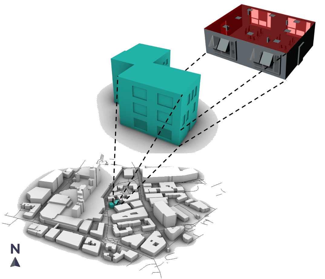
The following is one such example where we analyze a new low-rise building in the center of Nottingham, UK. The residential building under development has large commercial buildings surrounding it. The goal of this CFD analysis is to predict how the flow around the building affects the surrounding urban environment for wind comfort and in turn the comfort and natural ventilation of the building itself. A detailed wind comfort study is made around the interested building to assess the likely performance of a naturally ventilated ground floor office.
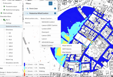
A pedestrian wind comfort analysis is set up using the CAD model of the residential building with its surroundings. To get detailed wind characteristics around the building, 8 wind directions were simulated using the integrated wind data from meteoblue. The influence of the building in the vicinity is assessed using the Lawson LDDC wind comfort criteria. Based on the geographical location of the study, there are specific wind comfort and wind safety criteria to determine if a space is suitable for certain pedestrian activities. A list of default wind comfort criteria available in SimScale can be found in this article.
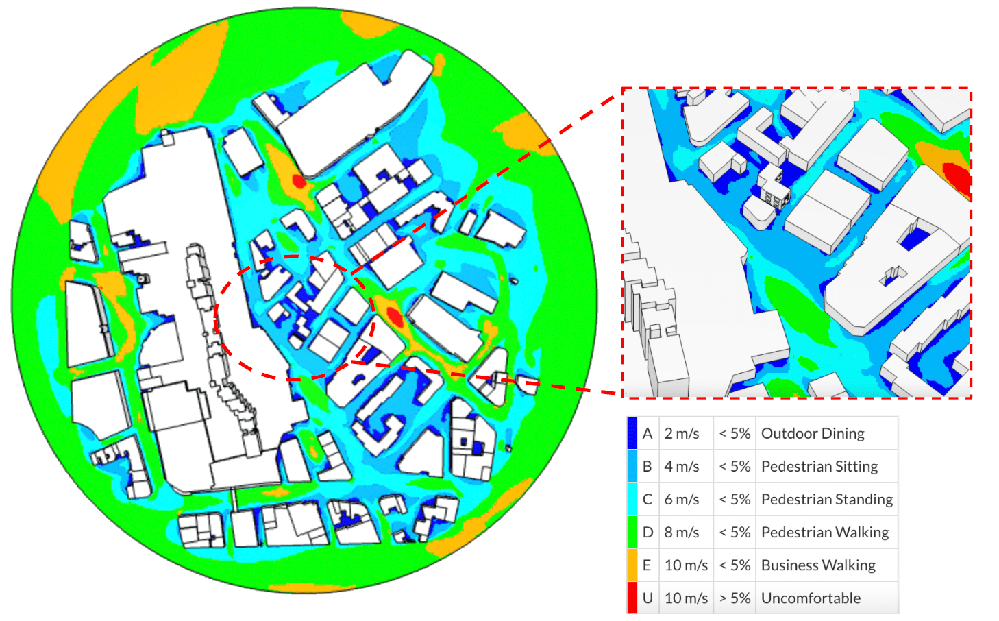
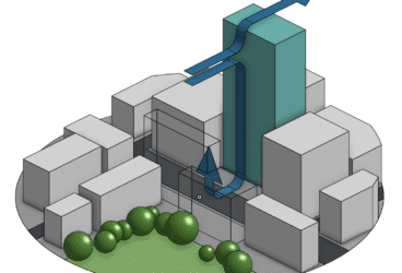
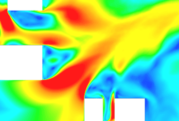
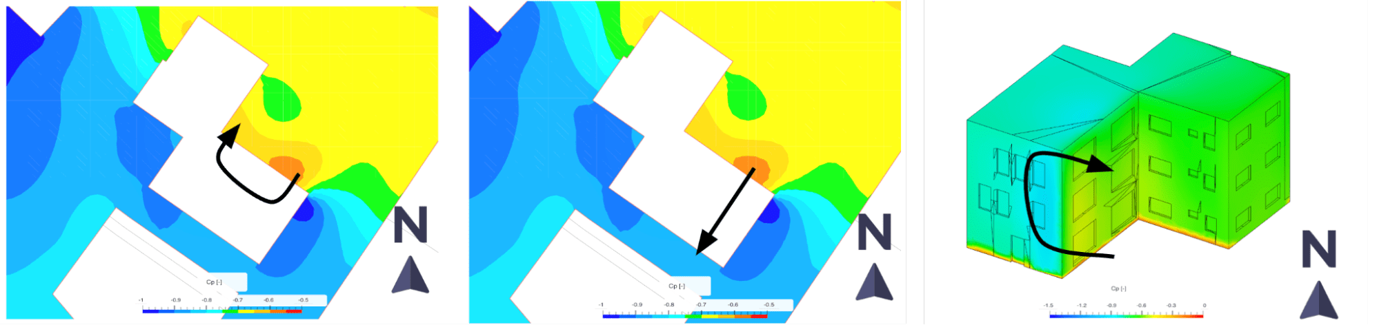
Wind criteria assessment shows that the area around the new building is well suited for most pedestrian activities. On the other hand, the secondary objective was to determine if the proposed site configuration can affect the ventilation requirements of the building’s ground floor. Wind pressure coefficients are usually used as inputs for simulations involving natural ventilation. Pressure coefficients can be obtained from CFD or wind tunnel tests, particularly in dense urban areas with complex context and topology. Air naturally flows from high pressure to low pressure, and we can use this information at an early stage to understand and control a building’s natural ventilation openings. Pressure coefficients provide an easy way to assess this, where higher values represent high pressure, and lower values represent lower pressure. Natural ventilation can be designed by changing the site layout, building shape, or even the addition of shapes to control flow such as trees and bushes. In addition to the pressure coefficients, the transient velocity and pressure results written out from the simulation can be used to predict the influence of 3D wind effects on ventilation.
Modeling the Indoor Environment
The thermal performance of building fabric has a significant impact on the energy and comfort performance of the building. The following CFD analysis describes the impact of choosing different building fabrics including insulation layers for the walls and window glazing.
The aim of this study is to quantify the total heat loss from surfaces and rooms in the building to assess the building’s efficiency in regard to the existing and modified building fabric. The considered building space has several HVAC supplies and outlets modeled according to a winter scenario.
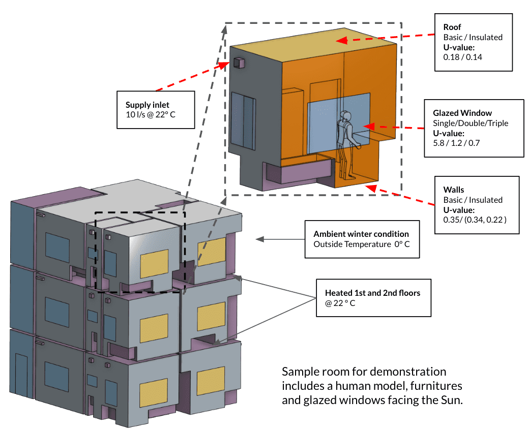
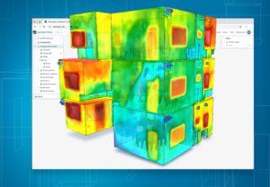
A 3D model of a three-story building is analyzed using the robust Conjugate Heat Transfer V2 analysis to determine its thermal efficiency. For demonstration purposes, a sample office room section with an occupant, furniture, and window facing the sun is the focus. The base configuration has specified U values on the walls and roof. The minimum requirements for the insulation are based on the Building Regulations – England. The table below encompasses six different variations in the level of insulation and glazing considered for this study.
| Design Variations | Description |
| Base | Single glazed – No insulation on external walls and roof |
| Variation 1 | Double glazed – No insulation on external walls – Insulated roof |
| Variation 2 | Double glazed – Wood insulation on external walls – Insulated roof |
| Variation 3 | Double glazed – Phenolic insulation on external walls – Insulated roof |
| Variation 4 | Triple glazed – No insulation on external walls – Insulated Roof |
| Variation 5 | Triple glazed – Wood insulation on external walls – Insulated Roof |
| Variation 6 | Triple glazed – Phenolic insulation on external walls – Insulated Roof |
The insulation and roof configurations based on the regulations are applied with layer wall thermal inputs in the simulation. Three window panel configurations were used in this study ranging from single to triple glazing with R values of 0.172, 0.833, and 1.429 respectively. The external walls are tested with wood fiber and phenolic foam insulations. The properties of the walls insulation are as follows:
- Wood Fibre
- R-Value: 2.95 (K m²/W)
- Phenolic Foam
- R-value: 4.65 (K m²/W)
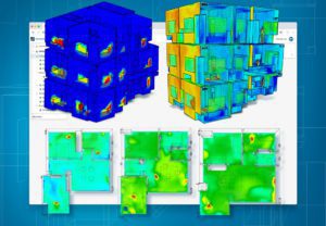
One of the key outputs from the simulation is the wall heat flux (W/m²) on the surfaces which gives us the amount of heat loss to predict the efficiency of the insulation layers and window glazing.
| Design Variations | Description | % Heat loss decrease (W) | Relative Increase in Room Temp (°C) |
| Variation 1 | Double glazed – No insulation on external walls – Insulated roof | 23.3 | 1.1 |
| Variation 2 | Double glazed – Wood insulation on external walls – Insulated roof | 24.15 | 1.3 |
| Variation 3 | Double glazed – Phenolic insulation on external walls – Insulated roof | 28.0 | 1.5 |
| Variation 4 | Triple glazed – No insulation on external walls – Insulated roof | 27.6 | 1.6 |
| Variation 5 | Triple glazed – Wood insulation on external walls – Insulated roof | 29.37 | 1.6 |
| Variation 6 | Triple glazed – Phenolic insulation on external walls – Insulated roof | 32.5 | 1.8 |
The relatively lower thermal conductivity of Phenolic foam provides an excellent insulation character to the walls, thereby restricting the flow of heat into the building. The results from variation 6 with Phenolic insulation on the external walls and an insulated roof leads to a total reduction of heat loss of about 33% when compared to the base configuration. This in turn improves the thermal comfort of the occupants inside the office room. The temperature measurement shows 16.5 °C at the human chest level.

How Can Architects and Engineers Get Started With Simulation?
SimScale enables architects and engineers to use cloud-native computational fluid dynamics (CFD) simulation to model:
- External wind comfort and safety
- Indoor thermal comfort and overheating
- Ventilation and air quality
- Solar gains and fabric energy efficiency
Designers can benefit from fast and accurate heat loss predictions, as well as the ability to visualize heat conduction through the building envelope, akin to those generated by thermal infrared photography.
Be sure to watch these on-demand webinars to learn more:
Simulating Building Performance
Learn how to simulate microclimate, thermal comfort, fabric energy efficiency, solar gains, and indoor air quality all from your web browser.

Fabric First: CFD for Passive Environmental Design
Learn how to model the thermal performance of the building fabric and evaluate energy efficiency options using powerful engineering simulation in the cloud.