The Tacoma Narrows Bridge is the historical name given to the twin suspension bridge—originally built in 1940—that spanned the Tacoma Narrows strait. It collapsed just four months later due to aeroelastic flutter. Since then, this topic has become popular, with several case studies discussing the failure phenomenon of suspension cable bridges.
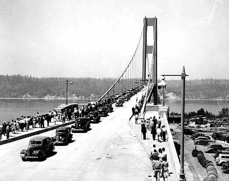
In the state of Washington, the construction of the Tacoma Narrows Bridge was completed and opened to traffic on July 1st, 1940. It was the very first bridge to incorporate a series of plate girders as roadbed support, and the first bridge of its type (cable suspension). It was also the third largest suspension bridge of its time, with a 2800-foot central span and two side spans of 1100 feet each.
A west-side approach had a continuous steel girder of 450ft, while the east side had a long reinforced concrete frame of 210ft. It had two cable anchorages of 26ft. along roadways, two 5ft. sidewalks, and two 8ft. deep stiffening girders. Among several other structural details, the suspension cable anchorages to which the cables were connected were made of 20,000 cubic yards of concrete, 6 lakh pounds of structural steel, and 2.7 lakh pounds of reinforcing steel. Because of its extremely long length, it was considered a ‘narrow bridge’. The overall construction cost was estimated to be a whopping $6 Million in 1940. Considering inflation, this is equivalent to almost $1 Billion, and all of this for something that lasted just four months and seven days. Yet, this remains a great engineering feature for civil engineers to ponder over.
The Incident: What Happened on That Fateful Day?
Shortly after the construction of the Tacoma bridge, it was found to dangerously buckle and sway along its length in windy conditions. Even with the normal winds, the bridge was undulating noticeably, and this had the engineers worried about the conditions in the presence of high winds. Alarmed by this, many engineers started conducting experiments in a wind tunnel on the structural behavior of the bridge when subjected to wind loads.
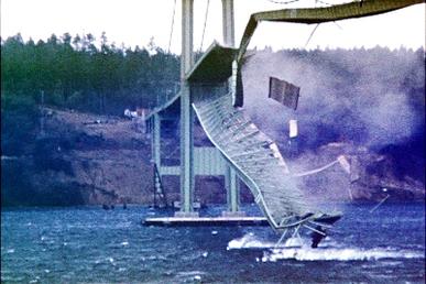
On the day of the Tacoma Narrows Bridge collapse, it experienced winds of about 19 m /s (i.e., about 70kmph). The center stay was torsionally vibrating at a frequency of 36 cpm (cycles/min) in nine different segments. Over the next hour, the torsional vibration amplitude built up, and the motion changed from rhythmically rising and falling to a two-wave twisting. Despite all these motions, the center part of the bridge (along the length) remained motionless, while its other two halves twisted in opposite directions.
The bridge was twisted noticeably into two parts, experiencing 14 vibrations/min. This drastic torsional motion was started by a failure of a cable (located along the north side) band connecting to the center of the diagonal ties. Due to alternative sagging and hogging of span members, the towers holding them were pulled towards them. Further, visible and predominant cracks developed before the entire bridge crashed down into the waters.
Thankfully, no human life was lost in the incident, but this was still an overwhelming engineering failure. Prof F.B Farquharson of the University of Washington was responsible for conducting experiments to understand the oscillations. On this day, the professor and his team recorded the movement of the bridge on camera, and we can find this today on YouTube.
Post-Investigation of the Tacoma Narrows Bridge Collapse
A three-dimensional scaled model of 1:200 scale was built for wind tunnel experiments and to explicitly understand the reason for failure. The experiments brought about a new theory: wind-induced oscillations. The image of the Tacoma Narrows Bridge collapse is shown in Fig. 03.
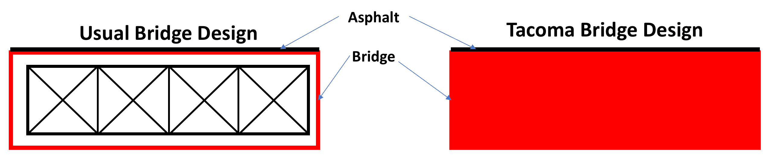
The shape of the bridge was aerodynamically unstable along the transverse direction. The vertical girders of the H-shape allowed flow separation, thus leading to vortex generation that matched the phase of oscillation. These vortices generated enough energy to push the girders out of their position.
The problem that caused the Tacoma Narrows Bridge collapse was not a new problem, but one which had been unspecified. Due to wind action, increased stiffness can be seen through various design methods such as adding a greater dead load, adopting dampers, stiffening trusses or by guy cables. However, these factors were not originally considered and only became part of the later forensics.
The Physics Behind the Tacoma Narrows Bridge Collapse
The Tacoma Narrows Bridge collapsed primarily due to the aeroelastic flutter. In ordinary bridge design, the wind is allowed to pass through the structure by incorporating trusses. In contrast, in the case of the Tacoma Narrows Bridge, it was forced to move above and below the structure, leading to flow separation. Such flow separation, in the presence of an object, can lead to the development of a Kármán vortex street, as the flow passes through the object.
The vortex frequency in the Kármán vortex street is the Strouhal frequency (fs) which is given by:
$$ f_s = \frac{U \cdot S}{D} $$
where U is flow velocity, D is the characteristic length and S is Strouhal number (a dimensionless quantity). Example: For a Reynolds number greater than 1000, S is 0.21. In the case of the Tacoma Bridge, D was 8 ft. and S was 0.20.
Bridge Design Using Simulation
After the Tacoma Narrows Bridge collapse, the new bridge was redesigned (based on lessons learned) and rebuilt in 1950 (Fig. 4). The newly built bridge incorporated open trusses (triangular), stiffening struts and allowed the wind to flow freely through openings in the roadbeds. Compared to the previous design, the twisting that developed in the new bridge was considerably less severe.
Because of the disaster of the Tacoma Narrows Bridge, the Whitestone Bridge in the US was strengthened by adding trusses and openings below road decks to decrease oscillations, and these are found to be working even today. The idea of using dynamic and modal analysis for the design of bridges received much greater impetus after this disaster.
The deflection theory serves as a model for complex analytical methods used by many structural engineers to obtain stresses, deflections, etc. This eventually led to the development of finite element analysis (FEA) as a generic tool for designing civil engineering structures.
Explore FEA in SimScale
Nowadays, in bridge design, engineering simulation plays a crucial part in the testing process. Using CFD to simulate wind loads and FEA to investigate stresses and the structural behavior of bridges, engineers can prevent failures like the Tacoma Narrows Bridge collapse and build better and stronger bridges and buildings.


