Piping design is essential for a wide range of applications, from oil and gas extraction and transportation to refineries, power stations, HVAC, plant engineering and cooling systems in engines and turbines. To ensure the functionality of the piping networks and improve their performance for fluid transportation, process engineers need efficient tools and solutions for piping design and optimization.
Pipe Design How to Begin a Piping Design?
Here are a few essential key factors to consider in the piping design process:
- Establish the optimum pipe diameter to guarantee optimum fluid flows for the pipeline system, depending on the specific fluid transportation needs
- Establish maximum and working flow pressure and temperatures
- Analyzing optimal pipe material composition depending on the chemical fluid properties
- Design pipeline network architecture for optimal fluid velocity
- Ensure safety factors and quality criteria for the whole pipeline design and pipeline network construction
The most common engineering problems that occur in piping design involve the fluid flow behavior and the analysis of stress in pipes networks. CFD simulation, as a fluid simulator, offers advanced methods to test them.
To easily understand the most important advantages offered by simulation software, let’s review some piping design simulation examples available in the SimScale Public Projects Library:
Thermal Thermal-Structural Analysis of a Cracked Pipe
Due to their extensive use, it is important to consider durability and damage tolerance for the whole life cycle of pipes. A crack in a pipe can result in an important loss of fluid, heat or steam with unpredictable consequences and significant damages costs. According to Pipeline & Hazardous Materials Safety Administration, in the last 20 years, pipeline incidents have caused over $6.3 billion in property damages. Statistics show 250 pipeline incidents per year, with an average of 2.5 million barrels spilled. [1]
In this thermal-structural analysis of a cracked pipe, the same simulation scenario considers a non-cracked and a cracked pipe. The CAD model was created with Onshape and then imported into the SimScale platform. For this analysis, a steady state thermal-structural analysis was selected, since the temperature and pressure were considered to be static.
If you’d like to learn more about how to use Onshape and SimScale together for a completely cloud-based design process, watch this free webinar recording.
CFD Scalar Transport in T-Junction Pipe
Experiments on piping design flow show that triggering turbulence depends sensitively on initial conditions. In real life, fluid flow turbulence generates many of the incidents, especially in the pipeline junction areas. This project simulates scalar transport mixing in turbulent T-junction pipe flow.
This project validates the mixing of a passive scalar quantity in a single phase flow at a Reynolds number of 24900 via the Reynolds-Averaged Navier–Stokes (RANS) approach and k-omega SST turbulence model. The geometry for this case is a T-junction pipe with two inlets.
The project simulates the mixing process at the junction and the scalar distribution downstream in the mixing pipe. The results give the contours of the scalar quantity and the flow field in the vicinity and downstream of the T-junction.
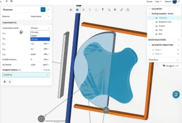
FEA Bending Analysis of an Aluminium Pipe
Structural analysis is frequently used in piping design and simulation process due to the elastoplastic behavior of aluminum or other piping materials. In this project, the bending of an aluminum pipe is done via a rolling process.
A nonlinear static structural analysis was selected. The penalty contact with higher stiffness was used for the contact between the pipe, roller, and molder. The results show the von Mises stress and total nonlinear strain formed in the bent aluminum pipe.
SIM Pipeline Network
The long-distance piping networks and junction’s architecture generate many problems for the piping maintenance in oil and gas and industrial water transportation.
This simulation project captures the nuances of turbulent pipe flow. With it, it is possible to visualize the flow phenomena at pipelines bends, junctions, and nozzles. The engineer created the geometry with Salome 7.4.0 and meshed on SimScale using the snappyHexMesh algorithm.
Non-Newtonian Flow of Concrete
In many practical applications, the piping system transports a mix of fluids with different physical properties and different behavior during the flow. One of these applications frequently used in the construction industry consists of concrete mixes. High slump or “flowing” concrete mixes are economical ready-mix products that allow a maximum flow without sacrificing strength by adding water at the job site.
This project simulates the flow of a non-Newtonian fluid (concrete) through a pipeline. The mixture mass proportions are 45% Gravel, 29% Sand, 9% Fine Sand, 17% Cement. The geometry constructed in Salome uses a CAD model of a ball valve.
The simulation shows the capability of the SimScale platform to model the behavior of non-Newtonian fluids; in this case, concrete.
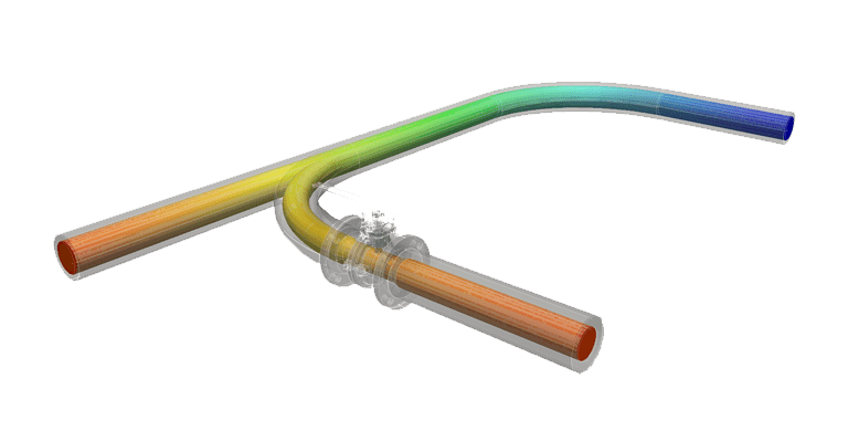
Comparison of Pipe Junction Designs
In pipeline design projects, engineers need to understand the pipe’s infrastructure behavior in different circumstances. Also, it is efficient to design two or more versions for the same pipe junctions.
Here is a good example of two different piping designs, simulated considering their downstream behavior. This project shows also how CFD can help in choosing the best design version. The main difference between the two models is the way the small pipe connects to the main pipe at the junction. Version one is a simple connection of both pipes. In version two, the small pipe continues into the larger pipe and opens up in the middle of the larger pipe.
For this project, the engineer chose an incompressible, steady-state simulation setup applying a k-omega SST turbulence model. The same simulation setup is used for both versions. If this model is used in the mixed flow of two fluids with very similar physical characteristics, the pipeline engineer will finally choose the version one, for a better efficiency. The simulation of both junction models also provides an immediate feedback on the performance. In this way, the design process progresses significantly faster.
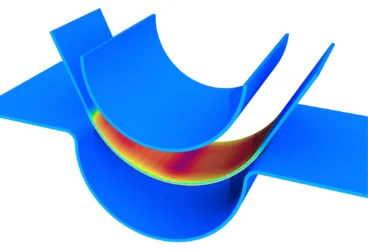
Pipe Hollow Drawing
This project demonstrates a simple simulation of a hollow manufacturing process. The simulation uses the nonlinear static stress analysis method.
Performed on an 8-core machine, the whole simulation took less than 2 hours.
The project also allows the analysis of the stress field, that results from the manufacturing process.
Aerodynamics of a Pipe with Vent Holes
Aerodynamics analyses are common across many industries. Even in the healthcare equipment industry, product engineers can simulate the flow aerodynamics inside different pieces of medical equipment.
This project shows firstly how to analyze the internal airflow through a medical device. For it, a fixed volume flux was applied at the inlet and a zero-gradient boundary condition at the outlet. A k-omega SST model is also used to account for turbulence effects. Finally, the steady-state simulation needed around 320 iterations to reach satisfying convergence criteria which took around 30 minutes on a 4-core machine. These kinds of simulation results can be also used to optimize the design in terms of the velocity peaks and the pressure drop of the device.
Creep Analysis of a Superheater Boiler Pipe
Superheaters increase the thermal efficiency of boiler equipment. They consist of several pipes which take the saturated steam and convert it into super-heated steam, in order to use it in steam engines, steam reforming, and other processes.
Working in a high steam pressure, superheater materials should also be resistant to industrial higher pressures and temperatures for extended periods of time.
In this project, the superheater pipe is tested for the high steam pressure and then the stresses relaxed for maximum 100,000 hours. Due to symmetry, simulation considers only part of the pipe.
Cyclic boundary conditions according to symmetry can be applied in order to represent the simulation for the whole pipe. The steam pressure of 10 MPa was also applied to the inner surface of a pipe.
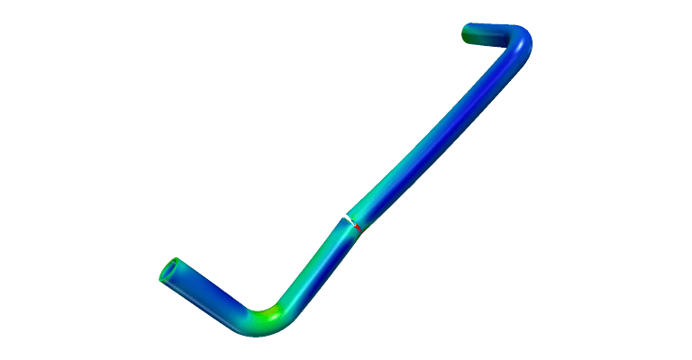
Pipe Elbow Joint
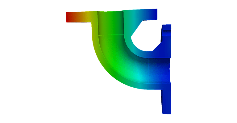
In piping design, engineers can combine straight tubular pipes in different configurations and for different tubing sections. The elbow joint is probably one of most common piping fit. Also, this is usually installed between two lengths of pipe to allow a change of direction. Here the vertical displacement is similar to bending in beams. The results show the von Mises stress, the vertical displacement, as well as weakest point of the elbow, which is the joint between the fixed flange and the elbow body at the bolt hole.
References
- Matthew Linnitt, Average 250 Pipeline Accidents Each Year, Billions Spent on Property Damage, April 2013, DesmogCanada