Fluid flow simulation can help produce a superior duct design in apparatus engineering in order to increase the performance of the overall system. This project provides a good example of the practical usage of CFD in plant engineering applications.
The Challenge
The installation situation of apparatus engineering devices can be critical for their performance. This project’s goal was to create a homogeneous flow field in front of the apparatus in order to enhance its performance.
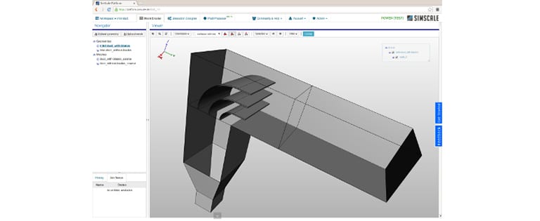
Duct Design Inlet Duct Design Simulation
Parallel to the duct design, the flow simulation capabilities of SimScale have been used to analyze the impact on the flow pattern for each design. It was possible to use the insights into the flow behavior gained from using SimScale to make early design decisions, without the overhead of testing and prototyping.
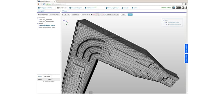
During the project, multiple simulations were carried out for multiple designs. One of the simulations took around 30 minutes on an 8-core machine. For a well-trained user, the simulation setup takes less than 10 minutes.
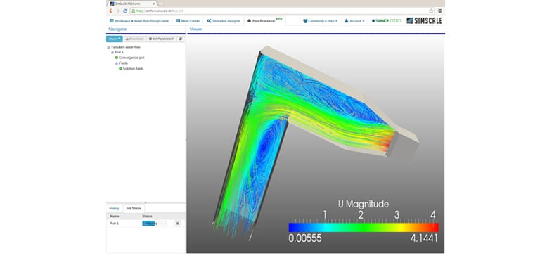
The image below shows the integrated post-processing environment of SimScale with a streamline visualization of the velocity field.
Duct Design Simulation Results
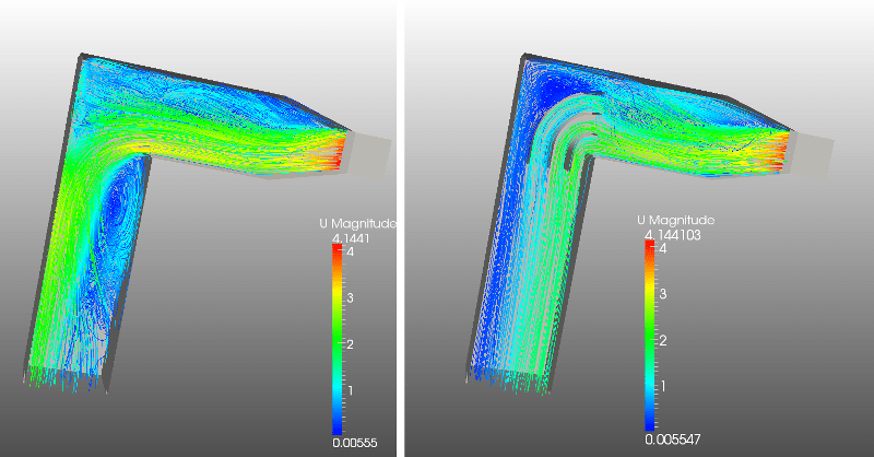
The results speak for themselves. The image below shows a color map visualization of the velocity field in the middle plane of two designs. The design on the left is the original version while in the design on the right, turning vanes have been added to the corner. The flow field near the outlet (on the left) is very inhomogeneous for the design without vanes. The reason for this flow behavior is the large recirculation region behind the corner of the duct. The design on the right shows a much more beneficial behavior: the airflow leaves the duct uniformly, which was this design project’s objective.
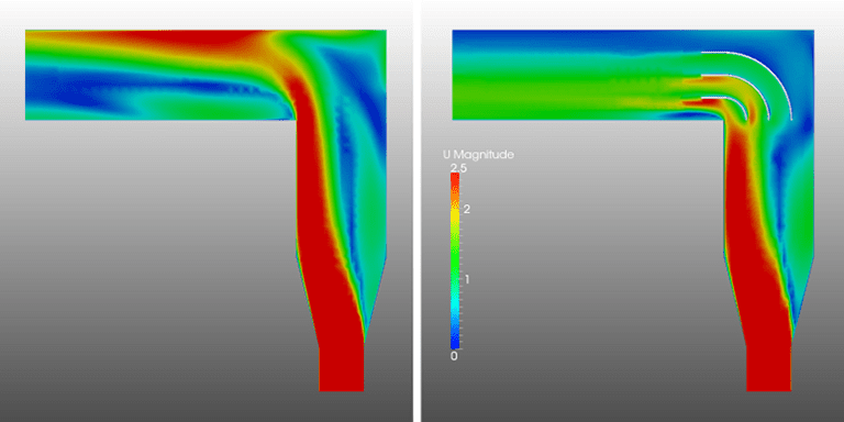
The streamline visualization of the velocity field below illustrates the reason for the resulting flow behavior more clearly. In the design without turning vanes, a large recirculation region appears behind the corner; in this design, the efficient flow channel is reduced to almost half of the channel width. This shows that investing a small amount of time in simulation while designing an inlet duct can significantly improve the performance of the overall system.
Sign up for a free community accountand perform your own simulation with SimScale.
Download this case study for free to learn how the SimScale CFD platform was used to investigate a ducting system and optimize its performance.